Quantcast
Channel: Sensor - Transducer - Detector Projects - PIC Microcontroller
Viewing all 136 articles
Browse latest View live

Heart rate measurement from fingertip

$
0
0

Heart rate measurement indicates the soundness of the human cardiovascular system. This project demonstrates a technique to measure the heart rate by sensing the variation of the blood volume inside a finger artery, which is caused by the pumping action of the heart. It consists of an infrared LED that transmits an IR signal through the fingertip of the subject.  A part of this infrared light is reflected by the blood cells. The reflected signal is detected by a photo diode sensor. The changing blood volume with heartbeat results in a train of pulses at the output of the photo diode, the magnitude of which is too small to be detected directly by a microcontroller. Therefore, a two-stage, high gain, active low pass filter is designed using two Operational Amplifiers (OpAmps) to filter and amplify the signal to appropriate voltage level so that the pulses can be counted by a microcontroller. The heart rate is displayed on a 3 digit seven segment LED display. The microcontroller used in this project is PIC16F628A.

Heart rate measurement from fingertip

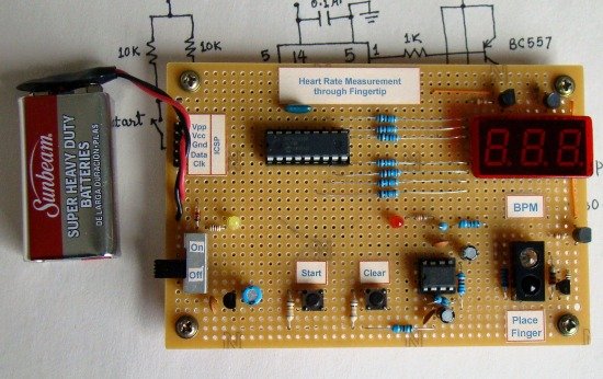
Heart rate measuring device using PIC16F628A

Theory

Heart rate is the number of heartbeats per unit of time and is usually expressed in beats per minute (bpm). In adults, a normal heart beats about 60 to 100 times a minute during resting condition. The resting heart rate is directly related to the health and fitness of a person, and hence is important to know. You can measure heart rate at any spot on the body where you can feel a pulse with your fingers. The most common places are wrist and neck. You can count the number of pulses within a certain interval (say 15 sec), and easily determine the heart rate in bpm.

This project describes a microcontroller based heart rate measuement system that uses optical sensors to measure the alteration in blood volume at fingertip with each heart beat. The sensor unit consists of an infrared light-emitting-diode (IR LED) and a photodiode, placed side by side as shown below. The IR diode transmits an infrared light into the fingertip (placed over the sensor unit), and the photodiode senses the portion of the light that is reflected back. The intensity of reflected light depends upon the blood volume inside the fingertip. So, each heart beat slightly alters the amount of reflected infrared light that can be detected by the photodiode. With a proper signal conditioning, this little change in the amplitude of the reflected light can be converted into a pulse. The pulses can be later counted by the microcontroller to determine the heart rate.
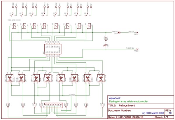
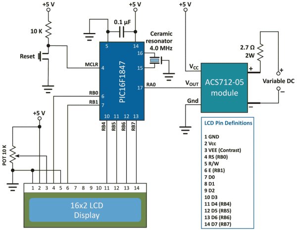
Circuit Diagram

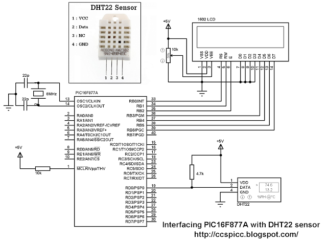
The signal conditioning circuit consists of two identical active low pass filters with a cut-off frequency of about 2.5 Hz. This means the maximum measurable heart rate is about 150 bpm. The operational amplifier IC used in this circuit is MCP602, a dual OpAmp chip from Microchip. It operates at a single power supply and provides rail-to-rail output swing. The filtering is necessary to block any higher frequency noises present in the signal. The gain of each filter stage is set to 101, giving the total amplification of about 10000. A 1 uF capacitor at the input of each stage is required to block the dc component in the signal. The equations for calculating gain and cut-off frequency of the active low pass filter are shown in the circuit diagram. The two stage amplifier/filter provides sufficient gain to boost the weak signal coming from the photo sensor unit and convert it into a pulse. An LED connected at the output blinks every time a heart beat is detected. The output from the signal conditioner goes to the T0CKI input of PIC16F628A.

Schematic Heart rate measurement from fingertip

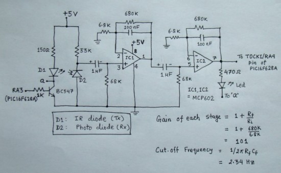
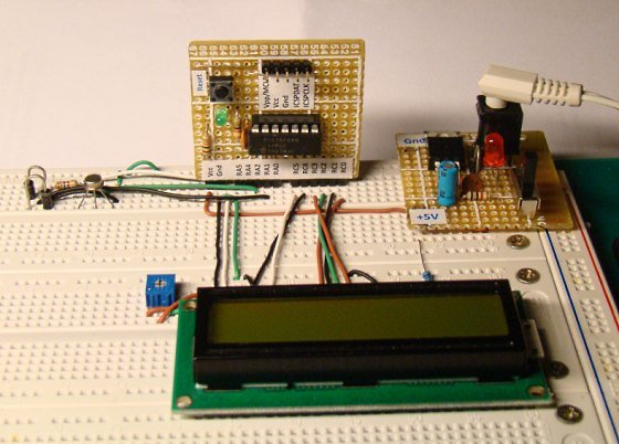
IR sensors and signal conditioning circuit

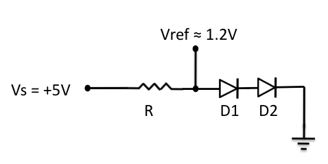
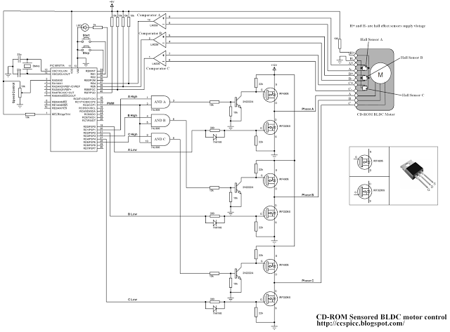
The control and display part of the circuit is shown below. The display unit comprises of a 3-digit, common anode, seven segment module that is driven using multiplexing technique. The segments a-g are driven through PORTB pins RB0-RB6, respectively. The unit’s, ten’s and hundred’s digits are multiplexed with RA2, RA1, and RA0 port pins. A tact switch input is connected to RB7 pin. This is to start the heart rate measurement. Once the start button is pressed, the microcontroller activates the IR transmission in the sensor unit for 15 sec. During this interval, the number of pulses arriving at the T0CKI input is counted. The actual heart rate would be 4 times the count value, and the resolution of measurement would be 4. You can see the IR transmission is controlled through RA3 pin of PIC16F628A. The microcontroller runs at 4.0 MHz using an external crystal. A regulated +5V power supply is derived from an external 9 V battery using an LM7805 regulator IC.

For more detail: Heart rate measurement from fingertip

The post Heart rate measurement from fingertip appeared first on PIC Microcontroller.


AquaCont – Aquarium Control using pic microcontroller

$
0
0

The AquaCont is an electronic system witch permits to manage and to monitor most of the parameters of all the electrics devices that can be found in a aquarium. The PIC18F4520 used to realize it, combines a real time clock and a temperature sensor in order to control 8 relays. The system main characteristics are:

 AquaCont  Aquarium Control

  • time / calendar

  • weekly timer for 6 daily events

  • digital temperature sensor

  • additional eeprom memory

  • 8 outputs controlled by relays joinables to timer events ( 2 of them that can be joined to temperature sensor)

  • LCD display 4×20

  • 8 bicolour LEDs associated to output ports

  • RS232 serial port for PC communication

The LCD display permits to monitor the current date and time, the temperature detected by the sensor and moreover it permits to visualize each port status in the last row. In the following LCD screens display it is possible to program the weekly timer events, set the temperature sensor parameters and manage the serial connection with a PC where is running the included WinTimer software.

The power supply needed by the main board is 5V, while the relays board requires 12V; the different source power was useful in granting the protection of the microcontroller and his circuits from overvoltage and short circuit on the 220V. Two optocouplers are utilized for that purpose ensuring the isolation of the different voltages.

 AquaCont  Aquarium ControlThe weekly timers are programmed basing on the clock provided by the proper integrated circuit supplied with a lithium battery. The timers data are memorized in the micro’s eeprom. The RS232 serial port allows to simply program the micro using the corresponding PC software; the functions provided in the PC software are also included in the firmware, except for the PC clock syncing. Using the Pc software is also possible to assign a description, to each of the 8 relays ports that will be memorized in the additional LC2416 eeprom memory. In this memory will be also stored the temperature sensor’s settings data.


For more detail:  AquaCont – Aquarium Control

The post AquaCont – Aquarium Control using pic microcontroller appeared first on PIC Microcontroller.

A Digital temperature meter using an LM35 temperature sensor

$
0
0

Introduction

A digital thermometer is a good choice of project for beginners who just stepped in to the world of microcontrollers because it provides an opportunity to learn using sensors to measure the real world signals that are analog in nature. This article describes a similar project based on a PIC16F688 microcontroller and an LM35 temperature sensor. LM35 is an analog sensor that converts the surrounding temperature to a proportional analog voltage. The output from the sensor is connected to one of the ADC channel inputs of the PIC16F688 microcontroller to derive the equivalent temperature value in digital format. The computed temperature is displayed in a 16×2 character LCD, in both °C and °F scales.A Digital temperature meter using an LM35 temperature sensor

Theory

The LM35 series of temperature sensors are produced by National Semiconductor Corporation and are rated to operate over a -55 °C to 150°C temperature range. These sensors do not require any external calibration and the  output voltage is proportional to the temperature. The scale factor for temperature to voltage conversion is 10 mV per °C. The LM35 series sensors come in different packages. The one I used is in a hermatic TO-46 transistor package where the metal case is connected to the negative pin (Gnd).

The measurement of negative temperatures (below 0°C) requires a negative voltage source. However, this project does not use any negative voltage source, and therefore will demonstrate the use of sensor for measuring temperatures above 0°C (up to 100°C).

The output voltage from the sensor is converted to a 10-bit digital number using the internal ADC of the PIC16F688. Since the voltage to be measured by the ADC ranges from 0 to 1.0V (that corresponds to maximum temperature range, 100 °C), the ADC requires a lower reference voltage (instead of the supply voltage Vdd = 5V) for A/D conversion in order to get better accuracy. The lower reference voltage can be provided using a Zener diode,  a resistor network, or sometime just simple diodes. You can derive an approximate 1.2V reference voltage by connecting two diodes and a resistor in series across the supply voltage, as shown below. As a demonstration, I am going to use this circuit in this project. I measured the output voltage across the two diodes as 1.196 V. The resistor R I used is of 3.6K, but you can use 1K too. The important thing is to measure the voltage across the two diodes as accurate as possible.Schematic A Digital temperature meter using an LM35 temperature sensor

We need do some math for A/D conversion. Our Vref is 1.196 V, and the ADC is 10-bit. So, any input voltage from 0-1.196 will be mapped to a digital number between 0-1023. The resolution of ADC is 1.196/1024 = 0.001168 V/Count. Therefore, the digital output corresponding to any input voltage Vin = Vin/0.001168. Now, lets see how to get the temperature back from this whole process of converting sensor’s output to 10-bit digital number.

For more detail: A Digital temperature meter using an LM35 temperature sensor

The post A Digital temperature meter using an LM35 temperature sensor appeared first on PIC Microcontroller.

Make your own motion sensor alarm with SMS feature using PIC18F2550

$
0
0

MikroEleketronika demonstrates how to build a simple home alarm system that has the capability of sending SMS to a predefined cell phone number when intrusion is detected.

motion sensor alarm

This project is based on StartUSB for PIC board, a small development board for PIC18F2550, which is preprogrammed with an USB bootloder so that no additional programmer is required to load the firmware. The SMS portion uses a SmartGM862 Board, which is a full-featured development tool for the Telit’s GM862 GSM/GPRS module. All the boards required for this project can be purchased as SMS Home Alarm Kit from mikroElektronika. A demonstration software for PIC is also available for free. They are offering free shipping now.


For more detail: Make your own motion sensor alarm with SMS feature using PIC18F2550

Current Project / Post can also be found using:

  • home automation program for microcontroller

The post Make your own motion sensor alarm with SMS feature using PIC18F2550 appeared first on PIC Microcontroller.

Digital humidity sensor using PIC microcontroller

$
0
0

Digital humidity sensor with LCD display using PIC microcontroller

Digital humidity sensor with LCD display is used to measure relative percentage  of water vapors in air. HS1101 capacitive humidity sensor is interfaced with PIC16F877A microcontroller to measure humidity and LCD is used to display percentage humidity in air.For humans there is certain limit for water vapors presence in air. Above that limit relative humidity may cause problems to human health.Digital humidity sensor using PIC microcontroller

Applications of digital humidity sensors

Humidity sensors have many application in industry and domestic areas. Humidity means presence of water vapors in air. Percentage of water vapors in air should be with in safety limit. Otherwise It have harmful physical and chemical effects on human beings and also in industrial products. Humidity sensors have major applications in agriculture ,chemical, oil, gas and medical industry. For example in agriculture industry humidity sensor is used to measure moisture in fields. There are also many other application of humidity sensor.You can search them om Google.

digital Humidity sensor selection

When you search on Google, you will come across many humidity sensors. All these humidity sensors have their advantage and disadvantage. But I used capacitive HS1101 humidity sensor in this project. What is meant by capacitive humidity sensor? All capactive senors give output in capacitive form.They change their capacitance with respect to change in sensing parameter like in HS1101 sensor sensing parameter is amount of water vapors in air. The reason why I used this humidity sensor?  Because

  • It can be used for highly sensitive applications.
  • less cost
  • easy to interface with microcontroller with small extra circuitry
  • No calibration is required
  • It can be easily used for home appliances and industrial control system.

How to use HS1101 digital humidity sensor

HS1101 is a  capacitive humidity sensor, so it can be used with 555 timer circuit to generate square wave of different frequency. I assume you know about 555 timer IC and its use.

Schematic Digital humidity sensor using PIC microcontroller

humidity sensor circuit with external circuitry

As shown in above figure, variable capacitor is used in place of humidity sensor for simulation purpose. Becuase HS1101 simulation model is not available in Proteus. Above circuit is used as a signal conditioning circuit to convert one form of parameter to its other proportional parameter so that it can be easily interfaced with any digital system or microcontroller. It is not possible for any microcontroller to read change in capacitance directly. That why above circuit is used to convert changing capacitance of HS1101 into sqaure wave whose frequency changed according to change in capacitance .

For more detail: Digital humidity sensor using PIC microcontroller

Current Project / Post can also be found using:

  • DIGITAL HUMIDITU SENSOR USING PIC MICROCONTROLLER

The post Digital humidity sensor using PIC microcontroller appeared first on PIC Microcontroller.

Green house intelligent control system

$
0
0

Green house intelligent control system is designed to protect the plants from more cool and hot weather and additional control system is included to save power by making fans and lights automatically turn on and off with the help of intelligent control system. In this project, the intelligent control system is developed using microcontroller and sensors. Green house system has a very important use now a days in the agriculture field.Some plants need the specific amount of water for their proper growth and more  productivity, therefore farmer should provide them the proper quantity of water. But it’s difficult for the farmer to get a estimation for quantity of moisture in soil. But in this project moisture sensor is used to to provide this facility with a intelligent control system.Green house intelligent control system

Block diagram below shows the main functionality of green house intelligent control system. Four sensors are used to measure different parameters of green house system which includes temperature sensor, light sensor, humidity sensor, moisture sensor. Four relays are used to control four respective loads as given below:

LM35 Temperature sensor :

When temperature becomes greater than 25 degree, respective relay become energize to operate the fan and when temperature becomes lower than 20-degree relay turn off the fan by getting control signals from microcontroller. PIC16F877A microcontroller analog to digital converter module is used to read temperature value and to operate relay which in turn operate the fan. To know more about temperature sensor and its working, go through the following article :

Digital temperature sensor using pic microcontroller
Light sensor :

Light dependent resistor is used as a light sensor. LDR is kind of variable resistor which resistance changes with the change in light intensity. So LDR resistance is converted into intensity of light by using LDR resistance and intensity of light formula. PIC16F877A microcontroller is used to measure intensity of light. When intensity of light fall under a certain limit, microcontroller provide signal to relay to turn on light and when intensity of light raise upto a certain limit , microcontroller provide signal to relay to turn off fan. So light sensor is used to add automatic light switching functionality in the green house system, if you don’t have much money to afford a gardener, then you can use green house intelligent control system to make your green house self-operating.

HS1101 Humidity sensor :

Humidity sensor is used to check level of moisture in air Because greater or less humidity level in air can also effect growth of plants. Humidity sensor HS1101 is used to measure level of moisture in air. HS1101 is a capacitative type humidity sensor, So additional circuit is used to convert change in capacitance of humidity sensor into frequency and frequency is measured with the help of microcontroller. Measured frequency is converted back into humidity using a algorithm in microcontroller programming. To know more about humidity sensor and its working, I suggest you to go through following article :

Digital humidity sensor using pic microcontroller 

If humidity becomes greater than a specified limit, microcontroller gives a signal to respective relay to turn on sprinter which is used to maintain a humidity level in the air and when humidity level comes back to a normal limit, microcontroller gives a signal to respective relay to turn off sprinter.


Moisture sensor :

Moisture sensor is used to measure level in soil. A wire strip is used to measure moisture of soil. Wire strip has a specific resistance at specific moisture, but when moisture increases, the resistance of wire strip starts decreasing and similarly when moisture decreases, resistance become higher. PIC16F877A used to measure moisture level and to turn on and off water pump with the help of relay.

Block diagram of complete project is shown below:

Schematic Green house intelligent control system

simulation of green house system

For more detail: Green house intelligent control system

The post Green house intelligent control system appeared first on PIC Microcontroller.

Automatic control of street lights

$
0
0

Automatic control of street lights is deigned to turn on and turn of street lights automatically. This project check the amount of light. If light is 80 percent available, it automatically turn off street lights. But if amount of light is less than 80 percent, this project will automatically turn on street lights. one can also adjust it according to its requirement. Light sensor is used to detect intensity of light. PIC161F877A microcontroller is used interfaced with light sensor to sense amount of light available. Control signal is generated with the help of pic16f877a microcontroller after analyzing amount of light. Control signal generated by pic microcontroller is used to turn on transistor which in turn energize the relay coil and relay turn on the street light. I have used only one lamp in this project. Because this is just for demonstration purpose. To use it practically, you can use as many street lights as many you want to control through this automatic control of street lights.Automatic control of street lights

This project have many applications. For example, you are too much lazy to turn on or turn off your street light manually and you forget to turn it on or off daily. So you easily use this project to save your electricity and in return your money. In countries where load shedding is a big issue due to short fall in electricity and less in resources to generate electricity. In these countries, load shedding issue can be resolved too some extent by saving as much as you can. By using automatic control of street lights, we can save maximum amount of energy which is useful for your nation and also beneficial for you. Because it will reduce you electricity bill and in return save your money.

Circuit description :

Followings are the main components of automatic control of street lights :

Light sensor :

Light sensor is used to sense amount of light. There are many light sensors available in market but Light dependent resistor (LDR) is used as a light sensor. Because it is cheap in price, easily available in market and can be easily interfaced with microcontroller to sense intensity of light. LDR have property to change its resistance according to intensity of light. If light is high, LDR will have low resistance and if light is low, LDR will have high resistance. So microcontroller can easily read this resistance in the form of voltage and which can be back converted into proportional value of light by using a formula available in data sheet.I recommend you to have look in data sheet of LDR.

Relay interfacing with microcontroller :

As I have already mentioned above that microcontroller is used to analyze intensity of light and to generate control signal which in turn on or off transistor which in turn energize relay to turn street light on or off. NPN transistor is used as a switch and resistor at the base of transistor is used as current limiting resistor. Diode is used to avoid back emf voltage which may produce sparking across relay.

Circuit diagram :

circuit diagram of automatic control of street lights is shown below :

Schematic Automatic control of street lights

circuit diagram of automatic control of street lights

For more detail: Automatic control of street lights

The post Automatic control of street lights appeared first on PIC Microcontroller.

Auto intensity control of street lights using pic microcontroller

$
0
0

Auto intensity control of street lights using  pic microcontroller, In this article you will learn how auto intensity control system of street lights works? How to control auto intensity of street lights? What is the purpose of auto intensity control of street lights? How you can design this project very easily using simple electronic components and pic16f877a microcontroller. Let’s start with basic introduction of auto intensity control of street lights.Auto intensity control of street lights using pic microcontroller

Auto intensity control of street lights :

Basic purpose of this project is to make street lights intelligent so that it can turn it on and off itself. Another feature of this project is that street lights intensity vary according to intensity of light and number of vehicles on road. Followings are the main features of this project :

  1. Street lights turns itself on automatically during night or darkness. They turn themself off automatically during day time and during visible intensity of light.
  2. Street lights controls its intensity automatically according to intensity of light. For example in evening intensity of light start decreasing at the same time street lights start increasing its intensity. When there is no intensity of light in after evening, street lights turn themself on with full intensity till midnight at 12:00 am.
  3. There is another feature included in this project that is vehicle detection. Infrared sensor circuit is used to detect vehicles on road. After 12:00am street lights start decreasing their intensity. At 1:00am street lights turn off automatically. After 1:00 am function of vehicle detection starts. If there is any vehicle on road after 1:00am, street lights turns on for 2 minutes. After that they turn off automatically. In other words, After 1:00am street lights turn on only if there is any vehicle on road. Otherwise they remain off. This process remains till morning. But after having visible intensity of light during moring street lights turn off automatically.

Advantages of auto intensity control of  street lights :

As it name suggest suggests it makes use of street lights very easy. Some of the main advantages of them are given below:

  • No need to control street lights manually.
  • Electrical power saving.
  • Increases life time of street lights.
  • intelligent street lights.
  • vehicle detection.

Circuit diagram description :

Followings are the main components of auto intensity control of street lights. I have explained all these components and their functions briefly.

DS1307 real time clcok:

DS1307 real time clock is use to keep information of time during day and night. Time is used to control intensity of light and its turn on and turn off ability after 12:00 am. So real time clock ds1307 is interfaced with pic microcontroler to keep information of real time.

Light dependent resistor ( LDR) :

Light dependent resistor is a kind of light sensor which is used to measure intensity of light. LDR is interfaced with pic16f877a microcontroller to measure intensity of light. This measured intensity of light is used to control street lights and their intensity.


Infrared sensor :

Infrared sensor is a combination of infrared transmitter and receiver. This is used  for detection of vehicles after 1:00 am. If there is any vehicle on road after 1:00am, street lights turns on automatically for 2 minutes otherwise remain off. I have already explained the main function of infrared sensor circuit for this project.

Light crystal display :

LCD ( liquid crystal display ) is used to display time and status of street lights. If street lights are on, LCD will display street lights are on, otherwise it display street lights are off.

Circuit diagram of auto intensity control of street lights:

complete circuit diagram of auto intensity control of street lights is given below :

Schematic Auto intensity control of street lights using pic microcontroller

circuit diagram of auto intensity control of street lights using pic microcontroller

For more detail: Auto intensity control of street lights using pic microcontroller

Current Project / Post can also be found using:

  • moving display diagram

The post Auto intensity control of street lights using pic microcontroller appeared first on PIC Microcontroller.


DS18S20 interfacing with pic and avr microcontroller

$
0
0

In this article you will learn how to interface temperature sensor DS18S20 with PIC16F877A microcontroller and atmega88 avr microcontroller. Complete interfacing circuit diagram and code for both PIC microcntroller and AVR microcontroller. DS18S20 interfacing with pic code is written using Mikro C for pic. Code for AVR microcontroller is written using Mikro basic complier for avr. Let’s start with basic introduction of DS18S20 digital thermometer.DS18S20 interfacing with pic and avr microcontroller

DS18S20 digital thermometer

DS18S20 is  9- bit digital thermometer which is used to measure celsius tempertaure. DS18S20 also have fuction of alaram with non-volatile user programmed points. It communicates with microcontrollers with only one wire. So it works with one wire communication protocol. It requires only one data line for communication. It can also be powered from data line. It remove the need of external power supply. Each DS18S20 have unique 32 bit address. Therefore it is  easy to interface multiple DS18S20’s with microcontroller.

DS18S20 applications

It have many applications. Some major applications are given below.

  • industrial temperature controller
  • buildings temperature controller
  • digital thermometers

DS18S20  features

It have following major features as compared to other digital thermometers:

  • one wire interfacing with microcontroller i.e. only one wire is required for data
  • alarm setting if temperature is outside permissible limits
  • Multiple devices can be interfaced with same microcotroller due to unique 64 bit address
  • Maximum accuracy
  • It can read temperature from -55°C to +125°C
  • No need of external components. It is ready to use by interfacing with microcontroller

DS18S20 pin configuration

It is available in 3 pin TO-92 package and 8 pin SO package as shown in figure below:

Schematic DS18S20 interfacing with pic and avr microcontroller

ds18s20 pin configuration

We are using 3 pin ds18s20 package in this tutorial.  Brief description of all the pins is given below:

  1. Number 1 : ground pin
  2. number 2: Data input and output pin. It is open drain one wire interfaced pin. It is also used for powered DS18S20.
  3. number 3:  5 volt power supply if not used in parasite power mode. if parasite power mode is used, it must be grounded

For more detail: DS18S20 interfacing with pic and avr microcontroller

The post DS18S20 interfacing with pic and avr microcontroller appeared first on PIC Microcontroller.

Programmable IR remote control using PIC16LF877

$
0
0

NEC-SIRCS-JAPAN-RC5-SAMSUNG compatible, multiprotocol infrared remote control.

Replaces up to 6 existing remote controls into one.

With manual learning function, LED display and/or LCD. 2V6-3V2, low power (sleep function)

More protocols will be added later if needed (DENON, DAEWOO, MOTOROLA, RECS80.)

Components: PIC16LF877-04/L (4Mhz PLCC Package), 24LC256 EEPROM (low power), 74HC148 encoder (SMD), optional Nokia 3310 graphic LCD (LPH-7779), IR LED, 5 optional LEDs, TSOP34836 IR receiver (low voltage)

All parts are available in our online shop

Schematic & pcb (Eagle 4.11e), source code (CCS) and hex file available.

More pictures.

Circuit explanation:

 IR remote

The main component is of course the PIC16LF877-04/L processor. Its 8K program ROM handles all inputs, outputs, timings and so on. There are six modes: SLEEP, IDLE, TRANSMIT, RECEIVE, BACKUP & RESTORE.

There are two displays available: LED and/or LCD. So you can choose freely which one suits you best. Naturally, the Nokia LCD gives us much more details as we will see further on.

Power consumption is only a couple of microamps in sleep mode !!The circuit is powered by two AAA batteries (HR03) These may be rechargeable types. The voltage can drop as low as 2,5V. The battery life is several months (although NI-Mh batteries lose 1% of their power each day!)

Sleep mode is activated automatically after 20 seconds of inactivity (no button pressed in idle mode.)

mode

consumption at 2V6 with Low Current-LEDs consumption at 2V6 with NOKIA LCD
sleep 1,2 to 2 µA (!) 1,2 to 2 µA (!)
idle 1,3 to 1,5 mA 1,3 to 1,5 mA
transmitting IR 11 to 17 mA 9 to 13 mA
receiving IR 2 to 10 mA 2 to 2,2 mA
backup or restore 5 mA 2,7 mA
 

All user data is stored in the 24LC256 i²c EEPROM. It contains 32768 bytes (8 pages of 4096 bytes.) That’s plenty! Pages 0 to 5 (0x0xxx to 0x5xxx) each contain data from the six devices (Aux, TV, Hifi, CD, DVD, Video) we are able to use. Page 6 is unused, page 7 stores all configuration data (f.e. which key is assigned to “PROGRAM” or to the device “DVD”…)

A maximum of 32 keys (4 columns by 8 rows) are supported. We have six fixed DEVICE SELECT keys (Aux, TV, Hifi, CD, DVD, Video), 1 fixed PROGRAM key , 1 fixed ENTER key. These eight fixed keys have to be programmed at the first power up (LCD shows “key init” “Program key?”, LEDs show “01000”) See more below. There are a maximum of 24 free COMMAND keys for each one of the six devices. Each free command key is protocol-free, this way we can mix protocols inside each device page.

RB4..7 are outputs to the four key columns. RB1..3 are inputs coming from the 8-bit HC148 encoder.

Whilst in sleep mode, pressing one of the keys on the key-matrix awakes the processor. The HC148, GS output which goes to to the PIC interrupt INT/RB0, goes low each time a key is pressed.

Also nice: the last device selected is stored in EEPROM. So, even unpowered, the circuit will keep all settings & data safe. You can even make a complete backup or restore of all data 😉

The IR receiver TSOP34836 (output comes low when a IR burst of around 36KHz detected) is powered only in program mode. The receiver takes only 0,7 mA but it’s still worth disabling while unneeded. More details about protocols & waveforms below.

For IR transmitting, there is of course an IR LED. It is boosted by a BC639. When enabled, it sends out  a burst of 37,1 kHz generated by the processor.

But, as you have guessed, all the rest is program code. More info under “source code explanation” below.


For more detail: Programmable IR remote control using PIC16LF877

Current Project / Post can also be found using:

  • Lan fohdi pik
  • LAN IC pic
  • lan relay mit pic controller bauen

The post Programmable IR remote control using PIC16LF877 appeared first on PIC Microcontroller.

A brief overview of Allegro ACS712 current sensor using PIC16F1847 (Part 1)

$
0
0

Sensing and controlling current flow is a fundamental requirement in a wide variety of applications including, over-current protection circuits, battery chargers, switching mode power supplies, digital watt meters, programmable current sources, etc. One of the simplest techniques of sensing current is to place a small value resistance (also known as Shunt resistor) in between the load and the ground and measure the voltage drop across it, which in fact, is proportional to the current flowing through it. Whereas this technique is easy and straightforward to implement, it may not be very precise because the value of the shunt resistor slightly varies with its temperature, which in fact is not constant because of the Joule heating. Besides, this simple technique does not provide an isolation between the load and current sensing unit, which is desirable in applications involving high voltage loads. Today, we will talk about Allegro ACS712 device which provides an economical and precise way of sensing AC and DC currents based on Hall-effect. This discussion is divided into two parts. The first part will provide a brief overview of the ACS712 sensor and its characteristics. In the second part, a test experiment will be carried out to interface the sensor with a PIC microcontroller to measure a dc current.

current sensor

Theory

The current sensing technique based on a shunt resistor is described in How to measure dc current with a microcontroller? and implemented in the Multi-functional power supply project. The major disadvantages of this technique are:

  • load is lifted from the direct ground connection
  • non-linearity in the response due to Joule heating that drifts the resistance value
  • lack of electrical isolation between the load and the sensing part

The Allergo ACS712 current sensor is based on the principle of Hall-effect, which was discovered by Dr. Edwin Hall in 1879. According to this principle, when a current carrying conductor is placed into a magnetic filed, a voltage is generated across its edges perpendicular to the directions of both the current and the magnetic field. It is illustrated in the figure shown below. A thin sheet of semiconductor material (called Hall element) is carrying a current (I) and is placed into a magnetic field (B) which is perpendicular to the direction of current flow. Due to the presence of Lorentz force, the distribution of current is no more uniform across the Hall element and therefore a potential difference is created across its edges perpendicular to the directions of both the current and the field. This voltage is known Hall voltage and its typical value is in the order of few microvolts. The Hall voltage is directly proportional to the magnitudes of I and B. So if one of them (I and B) is known, then the observed Hall voltage can be used to estimate the other.


For more detail: A brief overview of Allegro ACS712 current sensor using PIC16F1847 (Part 1)

The post A brief overview of Allegro ACS712 current sensor using PIC16F1847 (Part 1) appeared first on PIC Microcontroller.

Underground locator generator for Radiodetection using PIC16F628

$
0
0

Introduction

I obtained an early vintage Radiodetection® RD400 “LLTS” Precision Line Trace unit for a very low price through eBay. The RD400 is the receiver portion of a transmitter/receiver pair that comprise an underground cable locator system. Because the matching transmitter was not available (hence the low price,) I had to design one that matched the two audio frequencies detected by the receiver.

Underground locator generator

“LLTS” means Long Line Tracing System. Used with original transmitter, this unit was said to be capable of tracing signals in cables up to 45 miles. One of the most useful home-based applications of an underground locator is for locating breaks in the perimeter cable of underground dog fences!

Features

This transmitter is a simple design. The only control is a three-position rotary switch or center-off DPDT toggle switch. The transmitter is housed in a case that contains the 120VAC power cable, test cables, ground rod, and current clamp (not shown.)

Specifications

  • Power: 8-35VDC such as from a wall adapter for 120VAC 60Hz
  • Output: 512Hz or 8192Hz modified sine wave, 50-80VAC

Operation

Switch the unit on to either 512Hz or 8192Hz. The LED flashes slowly (1Hz rate) if 512Hz is selected; fast (16Hz rate) if 8192Hz is selected.

Underground locator generator schematic

The receiver detects the electromagnetic field generated by the transmitters signal in the underground cable. Because magnetics are involved, and because magnetic fields are induced by current flow, and because current cannot flow without a complete circuit, it requires that whatever means of connection to the underground cable is used, signal current must be caused to flow in the cable being detected. Therefore, some thought may be necessary to get a useful signal into an underground cable.

/****************************************************************************
underground_locator_tx.c

This program is a transmitter for an underground locator that operates at 512Hz or 8192Hz.

Transformer coupled, modified sine wave

WORKING CODE

                    +5
                     |
                    14
                ----------
               |      RA0 |-17-- output 1
  MODE   ----7-| RB1      |
               |      RA1 |-18-- output 2
               |          |
               |  16F628  |-1--- LED
               |          |
               |      RB6 |-12-- PGD
               |      RB7 |-13-- PGC
 20MHz XTAL-15-|     MCLR |-4--- MCLR
       XTAL-16-|          |
                ----------
                     5
                     |
                    Gnd

***************************************************************************/


For more detail: Underground locator generator for Radiodetection using PIC16F628

The post Underground locator generator for Radiodetection using PIC16F628 appeared first on PIC Microcontroller.

TDA7000 FM Receiver / TV Tuner / Aircraft Receiver using pic microcontoller

$
0
0
Parts:
1x TDA7000 IC – FM Receiver
1x 3.5 Turns Variable Coil (L1)
1x MV2105 – Varicap Diode
ANT – Telescopic Antenna
or a piece of wire

1x 100K Potentiometer
1x 100K Resistor
1 x 22K Resistor
3
x 100nF Capacitor
1x 22nF Capacitor 
1x 10nF Capacitor
2x 3.3nF Capacitor
1x 2.2nF Capacitor
1x 1nF Capacitor
2x 330pF Capacitor
2x 220pF Capacitor
2x 180pF Capacitor
1x 150pF Capacitor
  Technical Specifications:
Supply Voltage: 2 – 10V
Transmission Frequency: 70 – 120MHz
Power Consumption: 8mA
AF Audio Output: 75mV
TDA7000 FM Receiver TV Tuner  Aircraft ReceiverAbout TDA7000 FM Receiver / TV Tuner

TDA7000 is a great chip because it includes RF input stage, mixer, local oscillator, IF (intermediate frequency) Limiter, IF filter, amplifier, Phase demodulator, Mute detector, Frequency-Locked-Loop system and voltage controlled oscillator (VCO) all in a single chip, so you don’t have to do so much tuning and tweaking as you would normally do in super heterodyne receivers. TDA7000 is also a great choice for folks that don’t have great experience with RF circuits due to the fact that there are few external capacitors & resistors needed, no external IF filters, and only one variable coil and varicap diode.

The IC has an FLL (Frequency-Locked-Loop) system with an intermediate frequency of 70 kHz. The IF selectivity is obtained by active RC filters. The only function which needs alignment is the resonant circuit for the oscillator, thus selecting the reception frequency.

TDA7000 FM Receiver TV Tuner  Aircraft ReceiverSpurious reception is avoided by means of using a muting circuit similar to squelch. This eliminates and rejects other input signals around selected frequency so that even remote stations can sound clear just as if they were located near by.


For more detail: TDA7000 FM Receiver / TV Tuner / Aircraft Receiver

The post TDA7000 FM Receiver / TV Tuner / Aircraft Receiver using pic microcontoller appeared first on PIC Microcontroller.

Kaossilator 2 hack: hands free (part 1/2)

$
0
0

This is my first instructable…. ever. So here it goes.
Kaossilator 2 hack
I own a Kaossilator 2 (KO2). It’s fun little phrase synthesizer and simple looper. But it has this awkward issue with mic button. When you want to record something from microphone you have to hold down two buttons simultaneously. First the mic button to enable built-in microphone or external input (mic in) and second the loop recording bank button. This isn’t an issue until you want to connect another instrument to it and record a loop. While holding down two buttons you have only one hand free to express your self as best as you can.

Imagine that mic enable button is toggle switch. You could enable external input and hold down bank button with your foot and have both hands free. We are now one step closer to our goal. But you still need to put KO2 on the floor, record a loop and then pick it back up. This calls for an foot switch which I’ll be making in my second instructable.

Since Korg is reluctant to incorporate mic input toggle functionality in software update this could be solved with a little hardware hack. There are many ways to latch a push button. It can be done with transistor circuit, logic gates, NE555 timer or an microcontroller (MCU) and probably some other ways too. My favorite is MCU since it uses least amount of components and can be soldered directly on KO2s PCB.

Step 1: Look inside

hands free

First off let’s see what we are dealing with.
We see a nicely exposed signal line from SW7 to some resistors. This is a signal path of our mic button. Since there are no other components in the way we can just break the line and solder our MCU directly on the board.
Next thing to consider is that big black chip. Finding out functionality of its pins is important for tracing out the circuit. In our case the only pin that concerns us is Vdd 3.3V power line for our MCU.
Link to CY8C3244AXI-153 PSoC: http://www.cypress.com/?mpn=CY8C3244AXI-153
In datasheet we see that closest Vdd pins to our line are 26 and 100. And GND is everywhere. Entire mesh is GND.
So now we know where all of the signals that concern us are located.

Step 2: Choosing and programming MCU

MCU should be low pin count cause we only need two I/O pins. PIC10F series would be perfect for the job but they are not supported in mikroC PRO for PIC so I used the second best thing PIC12F series. I have few PIC12F675 chips lying around so I’ve used those. One in DIP package for breadboard and testing and one in SOIC package for soldering in KO2.
You could also use Atmel products:  ATtiny13, 25, 45, 85.
Or Texas Instruments products: MSP430G2210, MSP430G2230

The cheapest and best way to go is with Texas Instruments MSP430 LaunchPad flash programmer and debugger. 10$ and free shipping worldwide!

Attached source code has been modified since I took pictures of soldering so 3.3V for pullup resistor is no longer connected to GP0 I/O pin. With this new code you should connect pullup resistor directly between Vdd and GP1.

IDE I used: Mikroelektronika: mikroC PRO for PIC 5.4
MCU: PIC12F675
In project settings disable reset pin and set clock source as internal clock.
Project settings: Shift+Ctrl+E
Build project: Ctrl+F9

Lastly just flash your SOIC MCU. For flashing I used PICkit 2 programmer. Girls, you should too =P

Step 3: Preparing MCU

I’ve cut off unused pins so they don’t touch the PCB but not completely so I can make software updates in the future. Note that pullup resistor should now be connected to the upper left 3.3V pin instead of pin 7.

Step 4: Preparing PCB and soldering

First off put MCU on PCB and mark where pins touch the PCB traces and scrape off green solder mask to expose copper.
Then break the mic button signal path between the exposed copper pads.
Apply solder to the exposed copper pads. Applying solder is much easier if you use some flux.
Now all we need is power supply. If we trace from pin 26 we get to capacitor C8 and then to perfect soldering spot. Be sure to use insulated wire. Mine is from some inductor.


For more detail: Kaossilator 2 hack: hands free (part 1/2) 

The post Kaossilator 2 hack: hands free (part 1/2) appeared first on PIC Microcontroller.

TD-USB-02 interface with touchpad sensor board and WinAmp interface using PIC18F2550

$
0
0

TD-USB-02 interface with touchpad sensor board and WinAmp interface.

This is an example USB project showing how to interface a touchpad sensor (the AD7142ACPZ) with a standard XP/Vista computer.

The TD-USB-02 board with a PIC18F2550 communicates with:

  • the PC: USB 2.0 through a mini-B connector.
  • the touchpad sensor board: SPI over 8-wire flatcable.
  • PC WinAmp application controls (start/stop, next/previous track, volume up/down).

touchpad sensor board


Here are the technical specifications:

  • PC Win XP/Vista interface application with Visual C# 2008 Express: free download.
  • TD-USB-02 (green pcb on top) with PIC18F2550 USB HID setup.
  • TouchPad sensor board (047) with AD7142ACPZ.
  • USB Bus powered, no external power supply needed.
  • Activation of central wheel scrollpad and three buttons from any distance between 2-5mm.
  • Works from within a plastic enclosure, thickness up to 3-4mm.
  • Two LEDs (right above and under the centre button) blink when a pad is activated.
  • Custom command activated by top right button (example: “c:\windows\explorer.exe” )
  • TD-USB-02 software is 100% upgradable with a simple RS232 bootloader.
  • RS232 interface for raw data readings.
  • PCB Dimensions: TD-USB-02 40 x 41 mm or 1″57 x 1″61

These assembled boards are available from our online shop.

Source code (CCS C and Visual C#) can be purchased separately.


Sensor example Source code (CCS C) , sensor board pcb layout and schematics (Eagle) available. 

Last update: May 3, 2009.

TouchPad Board (047): Eagle PCB layout: 047_v005.brd  – Apr. 24, 2009.

 TouchPad Board (047): Eagle Schematics: 047_v005.sch  – Apr. 24, 2009.


 AD7142ACPZ: CCS c source code: touchpad_v01.c  – Apr. 24, 2009.

 TD-USB-02:Hex file: 047_v002.hex bootloading for the PIC18f2550  –  May 3, 2009.

 Windows interface application setup: 047_app_setup.zip  –  May 3, 2009. Written in Visual C# 2008 Express, compatible with Windows XP and Vista.


For more detail: TD-USB-02 interface with touchpad sensor board and WinAmp interface using PIC18F2550

The post TD-USB-02 interface with touchpad sensor board and WinAmp interface using PIC18F2550 appeared first on PIC Microcontroller.


Quozl’s Temperature Sensor Project using PIC12C509

$
0
0

Introduction

Just a handful of components builds an 8-pin microcontroller based circuit for temperature logging via a serial port; small, fast, and acceptably accurate.

Temperature Sensor

Features

  • provides real-time data to your computer via serial port,
  • interfaces up to four DS1820 temperature sensors,
  • absolute accuracy near 0.5 degrees celcius (as per DS1820 specifications),
  • relative accuracy near 0.01 degrees celcius,
  • speaks in Centigrade or Fahrenheit (selectable by header pins),
  • powered by your computer’s serial port, no extra supply to organise,
  • data format easily processed, no special programs required,
  • minimal parts count reduces cost,
  • built-in serial number for circuit identification,
  • special versions available for exotic requirements; high speed, low speed, additional sensors, long distance or pedantic serial bus.
  • spare inputs can be used as single-bit digital inputs, (feature removed from final version but can be re-inserted),

Applications

A few ideas of how this circuit can be used:

  • simple weather reports for web pages,
  • computer power supply temperature warnings,
  • redundant critical systems monitoring,
  • house temperature monitoring,
  • complex home automation tasks (start fan if warmer outside during winter),
  • refrigerator testing,
  • brewing temperature regulation,
  • fish tank heater verification,
  • microclimate logging (ground versus air temperature),
  • daylight sensing (LDR on digital input),
  • primitive locking (using serial number),
  • remote monitoring of emu fat in a freezer truck,

Availability

The electronics kit maker Kitsrushas released a PCB and kit of this design. Other kit sellers also sell the kit. Here is a summary:


Country Organisation Item Number GPL Compliance Date Checked
Australia Ozitronics K145 Complete 13th June 2003
United States of America Carl’s Electronics Inc CK110 Partial 13th June 2003
Kingston, Ontario, Canada QKits QK145 Complete 13th June 2003
Hong Kong Kitsrus K145 Complete 13th June 2003
Denmark eekit.dk 0104-K145 Partial 29th November 2004

(If you also sell this kit, and you would like to be added to the list, please write to me, including your country, organisation name, links to your web site and to the kit page. There is no reciprocal link condition. You may be asked to provide a link to this page, but that is for compliance with the software license.)


Theory of Operation
The program in the microcontroller knows two protocols; the one wire bus used by the DS1820 temperature sensor, and the serial protocol expected by your computer. Once power is applied, the program fetches data from the sensors and sends it to the serial port, repeatedly.


The data from the DS1820 arrives in a format peculiar to the sensor. The program calculates the temperature from the data and translates it into human readable ASCII digits. No special program is required on the computer.


Usage Instructions
Plug the circuit into the serial port of a computer. Persuade the computer to expect serial data at 2400 baud, 8 bits, no parity, one or two stop bits. Ask the computer to raise the DTR signal. (See below for software that will do this for you.) The microcontroller will start talking to the connected DS1820 sensors and the circuit should begin transmitting data to the computer. For example:


For more detail: Quozl’s Temperature Sensor Project using PIC12C509

The post Quozl’s Temperature Sensor Project using PIC12C509 appeared first on PIC Microcontroller.

A brief overview of Allegro ACS712 current sensor. Part 2 – Interface the sensor with a PIC microcontroller

$
0
0

In the first part of this discussion, the features of ACS712 device were briefly discussed. Now we will use that theory to implement the ACS712 sensor to make a simple DC current meter. The analog output voltage from the sensor is measured through an ADC channel of the PIC16F1847 microcontroller. A voltage to current conversion equation will be derived and implemented in the firmware of the PIC microcontroller and the actual load current will be displayed on a character LCD.

Experimental circuit setup

We are going to setup a test experiment to demonstrate the use of ACS712 to measure a DC current. I am using an ACS712-05B breakout module (you can find them cheap on ebay) for this purpose.

A brief overview of Allegro ACS712 current sensor. Part 2 - Interface the sensor with a PIC microcontrollerIt has got a 1 nF filter capacitor connected between pin 6 and ground, a 100 nF decoupling capacitor between power supply lines, and a power on LED soldered on the board. The power supply and output lines are accessible through header pins on one side, whereas, the current terminals are connected to a 2-pin terminal block on the opposite side, as shown below.

The experimental circuit diagram of the DC current meter is shown below. A 2.7 Ω (rated 2 Watt) resistor is connected in series with the current terminals and a varying dc voltage is applied to vary the current through the resistor and the current path. The output of the sensor module goes to AN0 (pin 17) ADC channel of the PIC16F1847 microcontroller. A 16×2 character LCD is used to display the measured current output.

I am using my PIC16F1847 breadboard module along with the Experimenter’s I/O board to demonstrate this experiment.

The microcontroller uses the supply voltage (+5V) as reference for A/D conversion. The digitized sensor output is processed through software to convert it to the actual current value. The mathematics involved in the process is described in the white board below.

For Vcc=5V and ADC Vref=5V, the relationship between output voltage and ADC Count is

But,

Important note: The calculations shown above considered supply voltage Vcc = Vref = 5.0 V. Interestingly, the final equation relating I and Count remains the same even the power supply fluctuates. For example, suppose Vcc fluctuates and becomes 4.0 V. Then, the sensitivity of the ACS712-05B also changes to 0.185 x 4/5 = 0.148 mV.

A brief overview of Allegro ACS712 current sensor. Part 2 - Interface the sensor with a PIC microcontroller SchematicIf you repeat the above calculations with Vcc = Vref = 4.0 V and sensitivity = 0.148 mV, you will end up with the same equation for I and Count. This was possible because of the ratiometric output of the ACS712 sensor.

The equation clearly tells that the current resolution for this setup is 26.4 mA, which corresponds to count 513, one count higher than the zero current offset. Therefore, this kind of arrangement is not suitable for measuring low current. You need an external Op-Amp circuit to enhance the resolution and be able to make more sensitive current measurement. If you are interested on that, you can visit Sparkfun’s ACS712 Low Current Sensor Breakout page that provides a circuit diagram for such an arrangement.


For more detail: A brief overview of Allegro ACS712 current sensor. Part 2 – Interface the sensor with a PIC microcontroller

The post A brief overview of Allegro ACS712 current sensor. Part 2 – Interface the sensor with a PIC microcontroller appeared first on PIC Microcontroller.

Sonar range finder using PIC16F88 Microcontroller

$
0
0

The PIC sonar range finder works by transmitting a short pulse of sound at a frequency inaudible to the ear (ultrasonic sound or ultrasound).

Afterwards the microcontroller listens for an echo.

The time from transmission to echo reception lets you calculate the distance from the object.

PIC Sonar Specification

Range ~5cm – 300cm
Accuracy +/-3cm
Transducer frequency 40kHz
nternal oscillator frequency 4MHz

The project uses 5 standard transistors to receive and transmit the ultrasound and a comparator to set the threshold echo detection level – so there are no special components other than the microcontroller.

The ultrasonic transducers are standard 40kHz types.

Note that the internal oscillator of the PIC micro is used and this saves two pins – that can be used for normal I/O,

You can recompile the pic sonar project files if you want examine code operation (using the built in simulator) or change the source code. Note the hex file is contained in the download.

PIC Sonar rangefinder

How the PIC Sonar rangefinder works

The time from transmission of the pulse to reception of the echo is the time taken for the sound energy to travel through the air to the object and back again.

Since the speed of sound is constant through air measuring the echo reflection time lets you calculate the distance to the object using the DST equation :

Distance = (s * t)/2 (in metres)

You need to divide by 2 as the distance is the round trip distance i.e. from transmitter to object and back again.

Where:

s [m/s] the speed of sound in air
t [s] the round trip echo time.

Some delay times:

Round trip echo time Distance
t = 588us 10cm
t = 5.8ms 1m

Note: The speed of sound in air is more or less constant at 330m/s (@ 0ºC) – it varies mainly with temperature (~340m/s @ 20ºC). In this project I am using a value of 340m/s i.e. it is assumed that the project is used indoors. You can change it to whatever you like by modifying the code.

You can get ultrasonic transducers optimized for 25kHz, 32kHz, 40kHz or wide bandwidth transducers. This project uses a 40kHz transducer but it will still work with the others if you make simple changes to the software (where it generates the 40kz signal). The receiver and generator circuits will work as they are.

Note: If you use a different transducer you must change the software to generate the correct frequency for the transducer as they only work at their specific operating frequency.

The 40kz signal is easily generated by the microcontroller but detection requires a sensitive amplifier. I have used a three transistor amplifier for the receiver.

This is followed by a peak detector and comparator which sets the sensitivity threshold so that false reflections (weaker signals) are ignored.

CCP – Capture mode

This project makes use of the CCP module (in its capture mode) to accurately measure the signal reception time at the CCP port pin. When a signal triggers the CCP module the value of timer 1 is stored in a CCP register (or captured).

If you store the value of timer 1 and then enable the CCP after transmitting an ultrasound pulse the CCP will trigger when the comparator activates i.e. as soon as an ultrasonic echo is received.

Subtracting the stored value from the CCP register value gives the time delay in machine cycles. Since the project uses a 4MHz main clock then the time delay will be measured in micro-seconds.

For more detail: Sonar range finder using PIC16F88 Microcontroller

The post Sonar range finder using PIC16F88 Microcontroller appeared first on PIC Microcontroller.

Sensored brushless DC (BLDC) motor control with PIC16F877A microcontroller

$
0
0
Sensored BLDC motor control using PIC16F877A – CCS PIC C compiler

This topic shows an easy way to drive a Cd-Rom sensored brushless DC motor (BLDC motor) using PIC16F877A microcontroller with CCS PIC C code.Sensored brushless DC (BLDC) motor control with PIC16F877A microcontroller

This motor is three phase motor, it has three stator phases that are excited two at a time to create arotating electric field. This method is fairly easy to implement, but to prevent the permanent magnet rotor from getting locked with the stator, the excitation on the stator must be sequenced in a specific manner while knowing the exact position of the rotor magnets.
The sensored BLDC motor has 3 hall effect sensors (Sensor A, Sensor B and Sensor C), this sensors sense the rotor position. Each sensor outputs a digital high for 180 electrical degrees and outputs a digital low for the other 180 electrical degrees. The following figure shows the relationship between the sensors outputs and the required motor drive voltages for phases A, B and C.

A three phase bridge is used to energize the BLDC motor windings.A three phase bridge is used to energize the BLDC motor windings.

Each phase driver requires 2 pins one for the high side and the other one for the low side which means a total of 6 pins are required to drive the three phase bridge. In this project 6 pins of PORTD will be used.
The 3 hall effect sensors needs 3 pins and for that RB4, RB5 and RB6 are used.

CD-ROM sensored brushless DC (BLDC) motor speed control with PIC16F877A microcontroller:
The following image shows project circuit schematic diagram.CD-ROM sensored brushless DC (BLDC) motor speed control with PIC16F877A microcontroller

LM339 consists of four independent precision voltage comparators. 3 camparators are needed for the 3 hall effect sensors as shown in the circuit schematic above. A +5V is needed for the LM339 chip as shown below:


For more detail: Sensored brushless DC (BLDC) motor control with PIC16F877A microcontroller

The post Sensored brushless DC (BLDC) motor control with PIC16F877A microcontroller appeared first on PIC Microcontroller.

Interfacing PIC16F877A with DHT22(AM2302-RHT03) sensor using CCS PIC C

$
0
0
Interfacing PIC16F877A with DHT22(AM2302-RHT03) digital humidity and temperature sensor
Interfacing PIC16F877A with DHT22(AM2302-RHT03) sensor using CCS PIC C
This topic shows how to interface PIC16F877A microcontroller with DHT22 sensor with hardware circuit.
Related topic:
The following topic shows PIC16F877A microcontroller and DHT22 Proteus simulation and some details about this sensor.
PIC16F877A and DHT22(AM2302, RHT03) sensor Proteus simulation
Interfacing PIC16F877A with DHT22(AM2302, RHT03) sensor circuit:
The following circuit schematic shows complete project circuit.Circuit Interfacing PIC16F877A with DHT22(AM2302-RHT03) sensor using CCS PIC C
The circuit is simple, there is the microcontroller PIC16F877A, DHT22 sensor and 1602 LCD to display humidity and temperature results.
Interfacing PIC16F877A with DHT22(AM2302, RHT03) sensor CCS C code:
The interfacing code is written with CCS PIC C compiler PCWHD version 5.051.
If you want to understand the code please read the DHT22 datasheet.

The post Interfacing PIC16F877A with DHT22(AM2302-RHT03) sensor using CCS PIC C appeared first on PIC Microcontroller.

Viewing all 136 articles
Browse latest View live


<script src="https://jsc.adskeeper.com/r/s/rssing.com.1596347.js" async> </script>