Quantcast
Channel: Sensor - Transducer - Detector Projects - PIC Microcontroller
Viewing all 136 articles
Browse latest View live

Nike+iPod reverse engineering (protocol too) using pic microcontroller

$
0
0

UPDATE: code posted below

Nike+iPod is a very interesting piece of hardware for all kinds of reasons, not the least of which is that it as actually useful. It works by wirelessly transmitting data from a sensor (that is stored in your shoe) to a receiver that is either externally connected to your iPod or to the receiver that is integrated into the bluetooth chip in the iPhone (3GS and 4 only). Some work has been done by others to try and figure out what data is sent by the sensor. This previous work can be seen here: 1, 2, and 3. As you can see, none of them really got far. They all failed to decode packet payload (which happens to be encrypted), they all failed to receive said data without using the stock receiver, and they all fail to understand the data. They only got as far as figuring out that there are 4 bits in there that are unique per sensor. Needless to say that this left me quite unsatisfied. I took a few days to figure out how it all works, and I am happy to say that I’ve decoded the entire packet payload successfully.

Nike+iPod reverse engineering (protocol too)Curiously those 4 bytes that everyone used for identifying the sensor uniquely are in fact NOT unique. If a tag’s serial number is “4A123456VSX”, then from those 4 bytes you can only define SOME of the digits of this serial number, not all. In fact for that particular tag, with just those 4 bytes you’d only get “_A123456___”.

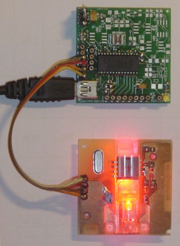
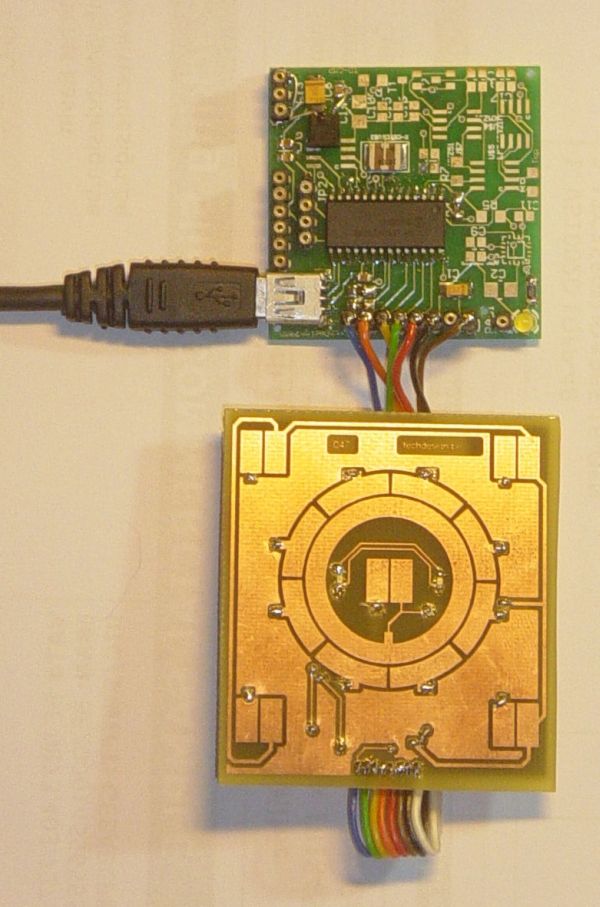
Hardware of the Nike+iPod sensor is quite interesting. I knew it used a nRF2402[Product page] to transmit the data. It’s a 2.4 GHz transmitter using GFSK modulation supporting 250Kbps or 1Mbps operation. It features a FIFO, and automatic packet assembly. That includes appending a “TO” address to the packet, sending a preamble byte, sending packet data, and sending a CRC as neeed. It is quite configurable. Channel is set in 1MHz increments, CRC choices are 0,8, or 16 bits. “TO” address can be anywhere from 0 to 5 bytes in 1 byte increments. This is a lot of options, and I had no time to guess what they chose. I opened to foot sensor and sniffed the configuration bytes sent to the nRF chip using a logic analizer. nRF2402 takes 2 configuration bytes on startup. Those bytes were: 0xE7 0x99. This tells us quite a lot. It tells us that the channel used is channel number 25, transmit power is set to maximum (1mW), data rate is 250 kbps, and 16-bit CRC is used. It also tells us some non-surprising things: ShockBurst is used, preamble is used. I also sniffed a lot of data frames here, and noticed that they all begin with the byte 0x0D. This may seem irrelevant now, but that will pass quickly. The packets are also 28 bytes long. Add in the 2 bytes of address and 2 bytes of CRC for the total RF payload of 32 bytes. One extra byte is sent for preamble. The TO address used in each message is “0xC2 0xBD”.

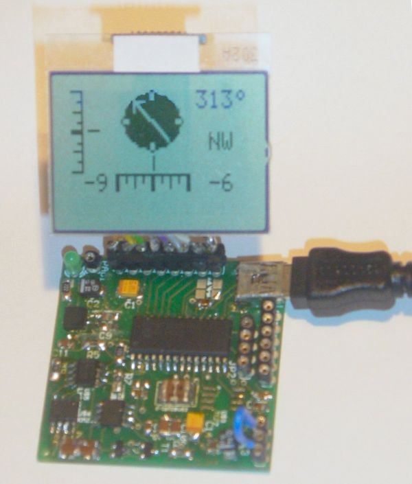
Recieving the data without the Nike+ receiver is difficult, which is why all other projects used said receiver. I had no desire to buy this receiver, and I am stubburn, so I looked for other ways. Nordic Semiconductor makes many other chips, and I happened to have one (nRF24L01+[Product Page]) around, on a breakout board from Sparkfun. This chip uses the same band, same modulation, same packet assembler/disassembler, and is by the same manufacturer – by all rules of logic it should be as good a receiver as anything. We hit the first snag as we read the datasheet and see that we need to use at least 3 address bytes to receive data. Well, this dashes our hopes, doesn’t it? Nah.

Nike+iPod reverse engineering (protocol too)
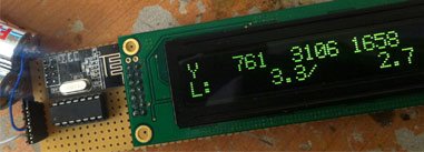
If you read carefully through all Nordic datasheets, you’ll see that the data length is never sent for these chips while using ShockBurst – both sides simply know it. Furthermore, the CRC is calculated over ADDR + DATA together, so realistically 2 bytes of address + 28 bytes of data is the same as 3 bytes of address + 27 bytes of data. This is where knowing that each packet begins with 0x0D helps. We tell our nRF24L01+ to receive on channel 25, expect 250 kbps, look for data length 27, 16-bit crc, and TO field of “0xC2 0xBD 0x0D”. Let’s turn it on and see what happens…. It works. We start getting packets: one a second. AWESOME! The sensor sends one packet every second as long as you walk or run, and for 10 seconds after you stop walking or running.


For more detail: Nike+iPod reverse engineering (protocol too)

The post Nike+iPod reverse engineering (protocol too) using pic microcontroller appeared first on PIC Microcontroller.


AquaCont – Aquarium Control using pic microcontroller

$
0
0

The AquaCont is an electronic system witch permits to manage and to monitor most of the parameters of all the electrics devices that can be found in a aquarium. The PIC18F4520 used to realize it, combines a real time clock and a temperature sensor in order to control 8 relays. The system main characteristics are:

 AquaCont  Aquarium Control

  • time / calendar

  • weekly timer for 6 daily events

  • digital temperature sensor

  • additional eeprom memory

  • 8 outputs controlled by relays joinables to timer events ( 2 of them that can be joined to temperature sensor)

  • LCD display 4×20

  • 8 bicolour LEDs associated to output ports

  • RS232 serial port for PC communication

The LCD display permits to monitor the current date and time, the temperature detected by the sensor and moreover it permits to visualize each port status in the last row. In the following LCD screens display it is possible to program the weekly timer events, set the temperature sensor parameters and manage the serial connection with a PC where is running the included WinTimer software.

The power supply needed by the main board is 5V, while the relays board requires 12V; the different source power was useful in granting the protection of the microcontroller and his circuits from overvoltage and short circuit on the 220V. Two optocouplers are utilized for that purpose ensuring the isolation of the different voltages.

 AquaCont  Aquarium ControlThe weekly timers are programmed basing on the clock provided by the proper integrated circuit supplied with a lithium battery. The timers data are memorized in the micro’s eeprom. The RS232 serial port allows to simply program the micro using the corresponding PC software; the functions provided in the PC software are also included in the firmware, except for the PC clock syncing. Using the Pc software is also possible to assign a description, to each of the 8 relays ports that will be memorized in the additional LC2416 eeprom memory. In this memory will be also stored the temperature sensor’s settings data.


For more detail:  AquaCont – Aquarium Control

The post AquaCont – Aquarium Control using pic microcontroller appeared first on PIC Microcontroller.

Digital Thermometer using PIC Microcontroller and LM35 Temperature Sensor

$
0
0

A Digital Thermometer can be easily constructed using a PIC Microcontroller and LM35 Temperature Sensor. LM35 series is a low cost and precision Integrated Circuit Temperature Sensor whose output voltage is proportional to Centigrade temperature scale. Thus LM35 has an advantage over other temperature sensors calibrated in Kelvin as the users don’t require subtraction of large constant voltage to obtain the required Centigrade temperature.

Digital Thermometer using PIC Microcontroller and LM35 Temperature SensorIt doesn’t requires any external calibration. It is produced by National Semiconductor and can operate over a -55 °C to 150 °C temperature range. Its output is linearly proportional to Centigrade Temperature Scale and it output changes by 10 mV per °C.

The LM35 Temperature Sensor has Zero offset voltage, which means that the Output = 0V,  at 0 °C. Thus for the maximum temperature value (150 °C), the maximum output voltage of the sensor would be 150 * 10 mV = 1.5V.  If we use the supply voltage (5V) as the Vref+ for Analog to Digital Conversion (ADC) the resolution will be poor as the input voltage will goes only up to 1.5V and the power supply voltage variations may affects ADC output. So it is better to use a stable low voltage above 1.5 as Vref+. We should supply Negative voltage instead of GND to LM35 for measuring negative Temperatures.

Digital Thermometer using PIC Microcontroller and LM35 Temperature SensorThis article only covers the basic working of Digital Thermometer using PIC Microcontroller and LM35, and uses 5V as Vref+. If you want more accurate results it is better to select Vref+ above 2.2V. I suggest you to use  MCP1525 IC manufactured by Microchip, which will provide precise output voltage 2.5.


For more detail: Digital Thermometer using PIC Microcontroller and LM35 Temperature Sensor

The post Digital Thermometer using PIC Microcontroller and LM35 Temperature Sensor appeared first on PIC Microcontroller.

TDA7000 FM Receiver / TV Tuner / Aircraft Receiver using pic microcontoller

$
0
0
Parts:
1x TDA7000 IC – FM Receiver
1x 3.5 Turns Variable Coil (L1)
1x MV2105 – Varicap Diode
ANT – Telescopic Antenna
or a piece of wire

1x 100K Potentiometer
1x 100K Resistor
1 x 22K Resistor
3
x 100nF Capacitor
1x 22nF Capacitor 
1x 10nF Capacitor
2x 3.3nF Capacitor
1x 2.2nF Capacitor
1x 1nF Capacitor
2x 330pF Capacitor
2x 220pF Capacitor
2x 180pF Capacitor
1x 150pF Capacitor
  Technical Specifications:
Supply Voltage: 2 – 10V
Transmission Frequency: 70 – 120MHz
Power Consumption: 8mA
AF Audio Output: 75mV
TDA7000 FM Receiver TV Tuner  Aircraft ReceiverAbout TDA7000 FM Receiver / TV Tuner

TDA7000 is a great chip because it includes RF input stage, mixer, local oscillator, IF (intermediate frequency) Limiter, IF filter, amplifier, Phase demodulator, Mute detector, Frequency-Locked-Loop system and voltage controlled oscillator (VCO) all in a single chip, so you don’t have to do so much tuning and tweaking as you would normally do in super heterodyne receivers. TDA7000 is also a great choice for folks that don’t have great experience with RF circuits due to the fact that there are few external capacitors & resistors needed, no external IF filters, and only one variable coil and varicap diode.

The IC has an FLL (Frequency-Locked-Loop) system with an intermediate frequency of 70 kHz. The IF selectivity is obtained by active RC filters. The only function which needs alignment is the resonant circuit for the oscillator, thus selecting the reception frequency.

TDA7000 FM Receiver TV Tuner  Aircraft ReceiverSpurious reception is avoided by means of using a muting circuit similar to squelch. This eliminates and rejects other input signals around selected frequency so that even remote stations can sound clear just as if they were located near by.


For more detail: TDA7000 FM Receiver / TV Tuner / Aircraft Receiver

Current Project / Post can also be found using:

  • Tv receiver pic micro

The post TDA7000 FM Receiver / TV Tuner / Aircraft Receiver using pic microcontoller appeared first on PIC Microcontroller.

Analog to Digital Converter Using PIC16f877A Microcontroller – Beginners Guide using pic microcontoller

$
0
0

What is meant by Analog to Digital Converter (ADC)? An ADC converts analog signal to it’s corresponding digital signal.

How to convert analog signal to digital signal? CircuitsGallery.com has already posted ADC using LM324 IC, in that ADC tutorial I had already explained Analog to Digital Converter how it works.
Analog to Digital Converter Using PIC16f877A MicrocontrollerWhile dealing with Microcontrollers we may face many situations where we have to use ADCs (Digital voltmeter, ammeter etc.). In such situations it’s difficult to set up a separate ADC hardware circuit for our project.

So How to Use Analog to Digital Converter (ADC module) in PIC microchip microcontroller? PIC microcontrollers have inbuilt ADC module making easy Analog to Digital conversion.

In this article I’m gonna show you how to make use of ADC module in PIC16F877A microcontroller with the help of Mikro C Pro compiler and Proteus 8 simulator.

At the end of this tutorial, I did the video demonstration and simulation about analog to digital conversion using PIC16f877a.

After reading this ADC tutorial, I’m sure that you will be able to program a PIC microcontroller for manipulating the ADC module. Come on let’s start PIC microcontroller programming.

Before going to the circuit diagram and embedded program, let me figure out some details about ADC in PIC and also ADC and inbuilt library functions in Mikro C.

ADC Register in PIC MCU

  • ADC (Analog to Digital Converter) module is offered in many of PIC MCU models.
  • The Analog-to-Digital (A/D) Converter module has eight inputs for the 40 pin PIC Microcontrollers.
  • In PIC16F877A, PORTA is multiplexed with ADC register, Comparator and Digital I/O operations. Due to the availability of ADC, PORTA is also known as Analog port.
  • In order to work on ADC we must configure the ADC register in proper way.
  • In PIC MCU, the conversion of an analog input signal effects in an equivalent 10-bit digital number (10 bit ADC).

Analog to Digital Converter Using PIC16f877A Microcontroller

Mikro C ADC Library and Important Library Routines for ADC Module

Micro C Library functions provide comfortable platform for working with ADC module in PIC. The only thing that we should add is the LCD library from the library manager.


For more detail: Analog to Digital Converter Using PIC16f877A Microcontroller

Current Project / Post can also be found using:

  • microchip pic analog signal

The post Analog to Digital Converter Using PIC16f877A Microcontroller – Beginners Guide using pic microcontoller appeared first on PIC Microcontroller.

Read analog values without an ADC using PIC12F675 microcontroller

$
0
0

Digital electronics and Analog electronics doesn’t mix easily. A Microcontroller can’t get analog values unless an Analog-to-Digital converter is used, however, you may find a little complicated the use of an ADC and it need lots of Input/Output ports.


Some Microcontrollers, like the small 8-pin Microchip PIC 12F675, do have an ADC integrated, but it is expensier than a PIC without ADC. A simple solution is to use a RC circuit to measure the resistance or capacitance.


Basically, a RC circuit is just a capacitor and a resistor. The circuit labeled A shows the most common RC circuit used. I like to use the B circuit, I get better results.

RC Circuit

You can replace the resistor and use a thermistor to measure temperature (PTC or NTC), also a photoresistor can be used to measure light. Any kind of resistive sensor can replace the resistor. If you are using a capacitive sensor, just replace the capacitor instead of the resistor.


How it works:

Just connect the RC circuit directly to an I/O pin of the microcontroller. You can use a 33pf capacitor and 1k resistor.


  • First, make the I/O pin as OUTPUT.
  • Second, make the pin POSITIVE (+) for one milisecond. (Using a PIC at 4mhz, a 255-cycles loop will be enough).
  • Third, Make the I/O pin as INPUT and measure how long stays as POSITIVE (+).An good application of this technique is my “One wire keypad”:

The PIC will measure the RC value of the I/O pin. If the time measured is too long, that means; there is no key pressed. Precision resistors and Mylar capacitor is required to get exact values.

You can see my ” Security Keypad ” uses a similar technique.

For more detail: Read analog values without an ADC using PIC12F675 microcontroller

Current Project / Post can also be found using:

  • Clap switch using adc port of microcontroller

The post Read analog values without an ADC using PIC12F675 microcontroller appeared first on PIC Microcontroller.

PICADC – a free, PIC based “intelligent” A/D converter using PIC16F84

$
0
0

This is an old design. Some of the components may be difficult to buy. If you would like to build an even better and cheaper A/D converter, take a look at the new PICADC3 design. The PICADC is a simple 12-bit, 8-channel analog to digital converter (with 4 additional digital inputs), which may be connected to the PC through the serial interface (RS232).

PIC AD converter
The sequence of sampled channels, and sampling frequence are programmed by the PC.
The maximal sampling frequency is limited by the data transmission rate, and at 115200 baud is equal to ca. 3kHz for 1 channel without digital inputs, and to ca. 500 Hz for 8 channel with digital inputs.
The analog input voltage range is -2.5V to 2.5V.
The digital inputs may be used for recording additional digital signals, eg. the time code used to synchronize the recorded data with other events.
The PICADC is based on PIC16F84 (or 166C84) microcontroller, and MAX190 (or MAX191) ADC.
The device is mounted on a small single-sided printed board, easy to prepare even at home, shown in the figure below (and available in the Easytrax for DOS format). There also printouts of the bottom layer, and top overlay available in the PDF format

Schematic PIC AD converter

The schematic diagram of PICADC is shown in the picture below, and is also available in the PDF format.

The R18 and R21 resistors are not mounted on my board. The R18 may be used to change the compensation mode of internal voltage reference in MAX190/191 (see the MAX190/191 data sheet), and R21 may be used to pull up the data line, when MAX190’s DOUT is in high impedance state.
The 4u7 capacitors (C4, C5, C7, C8, C10) should be tantalium capacitors (watch the polarity, when mounting them!).
The PICADC was intended to be a part of an optoisolated data acquisition system. Therefore its PCB does not contain the RESET circuitry and RS level converters, which should be connected through the transoptors. However usually the RESET switch is not needed and you can connect the ~RST pin (7) in the J2 connector to the +5V (J2 pin 8). If the optoisolation is not needed, you can use the MAX232 as the level converter, or simple circuits shown in the figure below:


For more detail: PICADC – a free, PIC based “intelligent” A/D converter using PIC16F84

The post PICADC – a free, PIC based “intelligent” A/D converter using PIC16F84 appeared first on PIC Microcontroller.

Build your own Wireless Network detector using PIC12F629

$
0
0

What This Is

This project is for a small electronic unit that allows the user to sense the presence and relative signal strength of wireless hotspots. It can be worn as a pendant or carried in a pocket. It is “always on” and communicates the presence and signal strength of an in-range hotspot by way of sequences of pulses – like a heartbeat you can feel. The stronger and faster the “heartbeat”, the stronger the wireless signal detected.

sensor guts illustrated

It does not actually authenticate or otherwise interact with a hotspot in any way. It is a 100% passive device, meaning it transmits nothing — it can detect hotspots, but cannot be detected itself.

How It Was Made

This project consists of a microcontroller, some custom interface electronics, a small vibe motor, and an off-the-shelf Wi-Fi detector – the one I used is by D-Link and is keychain-sized.

Here is the sensor I used, and some pictures of the construction. Details of the design will follow.

How It Works

The microcontroller periodically “presses” the button on the detector to initiate a reading. Then the microcontroller “reads” the output from the indicator LEDs on the detector, and uses this as the basis for pulsing out a signal on the vibe motor, which the wearer can feel.

In this way, the unit keeps you updated on the presence and signal strength of a wireless hotspot in your vicinity. No pulses means no signal. Short pulses means a weak signal. Faster, more frequent pulses means a stronger signal. This feedback is very much like a heartbeat, and is extremely intuitive to interpret.

How To Make Your Own

First of all, I use a microcontroller in this project. If you aren’t familiar with terms like 12F629 or .HEX files and how to blast them into a PIC, you will have trouble with this project.

The D-Link sensor I used works like this — press the button and the LEDs light up in a “scanning” pattern while it looks for a signal. It can be in this scanning pattern for up to a few seconds. Afterwards, it lights up either one, two, three, or four of the green LEDs to indicate relative signal strength. If there is no signal detected, a single red LED is lit. The LED(s) remain lit for a few seconds, then the sensor shuts off.

If your chosen sensor works differently, you will need to adjust the electronic interface and the program in the microcontroller accordingly.


For more detail: Build your own Wireless Network detector using PIC12F629

Current Project / Post can also be found using:

  • pic ethernet
  • skema tda7000 varactor

The post Build your own Wireless Network detector using PIC12F629 appeared first on PIC Microcontroller.


A brief overview of Allegro ACS712 current sensor using PIC16F1847 (Part 1)

$
0
0

Sensing and controlling current flow is a fundamental requirement in a wide variety of applications including, over-current protection circuits, battery chargers, switching mode power supplies, digital watt meters, programmable current sources, etc. One of the simplest techniques of sensing current is to place a small value resistance (also known as Shunt resistor) in between the load and the ground and measure the voltage drop across it, which in fact, is proportional to the current flowing through it. Whereas this technique is easy and straightforward to implement, it may not be very precise because the value of the shunt resistor slightly varies with its temperature, which in fact is not constant because of the Joule heating. Besides, this simple technique does not provide an isolation between the load and current sensing unit, which is desirable in applications involving high voltage loads. Today, we will talk about Allegro ACS712 device which provides an economical and precise way of sensing AC and DC currents based on Hall-effect. This discussion is divided into two parts. The first part will provide a brief overview of the ACS712 sensor and its characteristics. In the second part, a test experiment will be carried out to interface the sensor with a PIC microcontroller to measure a dc current.

current sensor

Theory

The current sensing technique based on a shunt resistor is described in How to measure dc current with a microcontroller? and implemented in the Multi-functional power supply project. The major disadvantages of this technique are:

  • load is lifted from the direct ground connection
  • non-linearity in the response due to Joule heating that drifts the resistance value
  • lack of electrical isolation between the load and the sensing part

The Allergo ACS712 current sensor is based on the principle of Hall-effect, which was discovered by Dr. Edwin Hall in 1879. According to this principle, when a current carrying conductor is placed into a magnetic filed, a voltage is generated across its edges perpendicular to the directions of both the current and the magnetic field. It is illustrated in the figure shown below. A thin sheet of semiconductor material (called Hall element) is carrying a current (I) and is placed into a magnetic field (B) which is perpendicular to the direction of current flow. Due to the presence of Lorentz force, the distribution of current is no more uniform across the Hall element and therefore a potential difference is created across its edges perpendicular to the directions of both the current and the field. This voltage is known Hall voltage and its typical value is in the order of few microvolts. The Hall voltage is directly proportional to the magnitudes of I and B. So if one of them (I and B) is known, then the observed Hall voltage can be used to estimate the other.


For more detail: A brief overview of Allegro ACS712 current sensor using PIC16F1847 (Part 1)

The post A brief overview of Allegro ACS712 current sensor using PIC16F1847 (Part 1) appeared first on PIC Microcontroller.

Humidity and temperature measurements with Sensirion’s SHT1x/SHT7x sensors using PIC18F2550 (Part 1)

$
0
0

Temperature and relative humidity are two very important ambient parameters that are directly related to human comfort. Sometimes, you may be able to bear higher temperatures, if there is a lower relative humidity, such as in hot and dry desert-like environment. However, being in a humid place with not very high temperature may make you feel like melting. This is because if there is high relative humidity, sweat from our body will evaporate less into the air and we feel much hotter than the actual temperature. Humidifiers and dehumidifiers help to keep indoor humidity at a comfortable level. Today we will discuss about Sensirion’s SHT series of digital sensors, more specifically SHT11 and SHT75, which are capable of measuring both temperature and relative humidity and provide fully calibrated digital outputs. We will interface both the sensors to PIC18F2550 microcontroller and compare the two sets of  measurements to see the consistency between the two sensors. This tutorial is divided into two parts. The first part will cover all the details regarding the sensors, including their specification, interface, and communication protocol. The second part will be more focussed on the circuit diagram, implementation of the communication protocol with PICMicro, and the results.

Sensirion’s SHT1x

Theory

Sensirion offers multiple SHT series of digital sensors for measuring both relative humidity and temperature. The temperature is measured using a band-gap sensor, whereas the humidity sensor is capacitive; which means the presence of moisture in air changes the dielectric constant of the material in between the two plates of a parallel-plate capacitor, and hence varies the capacitance. The required signal conditioning, analog-to-digital conversion, and digital interface circuitries are all integrated onto the sensor chip. The various SHT series sensors have different levels of accuracy for humidity and temperature measurements, as described below.

SHT1x, 2x, and 7x series of humidity sensors (Source: http://www.sensirion.com)

SHT1x are available in surface mount type whereas SHT7x are supplied with four pins which allows easy connection. The SHT11 and SHT75 sensors both provide fully calibrated digital outputs that can be read through a two-wire (SDA for data and SCK for clock) serial interface which looks like I2C but actually it is not compatible with I2C. An external pull-up resistor is required to pull the signal high on the SDA line. However, the SCK line could be driven without any pull-up resistor. The signaling detail of the serial bus is described in the datasheet, which we will implement for PIC18F2550 microcontroller using mikroC pro for PIC compiler. The operating range of both the sensors is 0 to 100% for relative humidity, and -40.0 to 123.8 °C for temperature. The sensor consumes 3 mW power during measurement, and 5 μW, while in sleep mode.

The SHT11 module that I have got is from mikroElektronika. The sensor (SMD) is soldered on a tiny proto board with all the four pins accessible through a standard 0.1 inch spacing male header. The board comes with pull-up resistors connected to both SDA and SCK lines. One concern in this type of arrangement is the heat dissipated by the pull-up resistors could affect the measurements if the resistors and the sensor are close in the board. We will discuss about this issue later too. The SHT75 module from Sensirion, however, does not include any pull-up resistor for SDA line and therefore must be included externally.


For more detial: Humidity and temperature measurements with Sensirion’s SHT1x/SHT7x sensors using PIC18F2550 (Part 1)

The post Humidity and temperature measurements with Sensirion’s SHT1x/SHT7x sensors using PIC18F2550 (Part 1) appeared first on PIC Microcontroller.

Whistle Key Finder using PIC12F629

$
0
0

This project uses one of the smallest chips in the PIC microcontroller range, the PIC12F629 and you can learn to program it and experience the thrill of making something yourself and see what goes into writing a program.
Even a program as simple as this one is not easy to put together and if you are starting from scratch, you will need a programmer (a “burner”) and all the data that goes with “burning” and creating a program for the micro. We use the PICkit-2 as it is the cheapest and best. It comes with USB cable and 2 CD’s containing the programs needed to “burn” the chip. You will also need NotePad2 to write your .asm program
(use Whistle.asm or Whistle.txt as a template for your program).

Whistle Key Finder

The PC board includes 5 pins for “In Circuit Programming” via PICkit-2 and you will be encouraged to use surface-mount components to interface the piezo diaphragm to the chip.
One of the clever parts of the circuit is the piezo is used to detect the sound and then produce the beep-beep-beep reply.
Be reminded that not all piezo diaphragms are the same. Some are very sensitive when detecting audio and others are not sensitive at all.
Ours produces an output of about 20mV to 50mV when whistling up-close, while an insensitive diaphragm will produce only a few millivolts.

The CIRCUIT
The circuit consists of two common-emitter stages with enough gain to produce a rail-to-rail signal when the piezo detects a whistle.
We are not concerned about distortion or over-driving the chip as we want a fairly square wave.
A super-alpha arrangement was tried using two transistors but it did not work at all.
It is surprising how “theory” does not always work in practice and that’s why you must try everything before settling on a result. Each stage has a gain of approx 70, making the total approx 5,000. This allows a 1mV signal from the piezo to produce a rail-to-rail waveform.
As we mentioned, the interesting feature of the circuit is the use of the piezo to detect a signal and then produce a beep. This has been done by making the piezo “float.”
It is not connected to any rail and although it is connected to pins of the chip, these can be made “inputs” and thus become high impedance.
The 4k7 on the base of the transistor allows the piezo to be driven by the chip in “bridge-mode” where the pins are alternately made high then low so that twice the supply voltage is effectively delivered across the piezo to increase its output.
Without the 4k7, the lead of the piezo would not rise above 0.6v due to the base-emitter voltage limitation.
When the piezo is required to detect a signal, one lead is connected to 0v via a pin of the chip and the other lead connects to the base via the 4k7. The pin on the chip is changed to “input” during this operation.
When the piezo is activated, the signal is also amplified through the transistors but the chip is not in detection-mode and this signal is not detected.

SURFACE-MOUNT COMPONENTS
To keep in line with miniaturisation, we have used surface-mount components. Once you start using surface-mount components, you get hooked. Through-hole components seem enormous. You will need fine tweezers to hold them in place while one end is soldered.
Always use very fine solder as you only need very little for each component and the main reason for adding extra is to take advantage of the flux to clean the connection. Always solder resistors with the value showing. Capacitors don’t have values marked on them and you cannot work out the value by the size of the component.
That’s why you have to know the value before taking them out of their “carrier.”

CONSTRUCTION
You can build the circuit on any type of PC board and we have used a small prototype board that needs some of the tracks cut to suit the placement of the 8 pin IC socket.
The kit of components comes with all the parts you need to get the project working, including a pre-programmed chip and a prototype PC board that needs some tracks cut.
We will not describe any construction details as most constructors will be adept in placing components. The only thing to remember is to cut the tracks before fitting the IC socket as some tracks run under the socket.

To modify the program you will need a PICkit-2 programmer and this comes with 2 CD’s containing all the software needed for In-Circuit Programming.
You will also need a lead to connect the programmer to your lap top via the USB port (comes with PICkit-2) and an adapter we call a 6pin to 5 pin Adapter to connect the PICkit-2 to your project. (The photo below shows the prototype 6pin to 5 pin Adapter. A PC board is now available for the adapter.)


For more detail: Whistle Key Finder using PIC12F629

The post Whistle Key Finder using PIC12F629 appeared first on PIC Microcontroller.

Roll and Temperature sensor applications using PIC18F2550

$
0
0

This page will show you how to use the TD-CMP modules in a way which fits you most.


Here are the technical specifications of the modules:

  • Compass: Resolution: 1° – Accuracy: 3°
  • Tilt/Roll: (TD-CMP02 and TD-CMP03 only) Resolution: 2° – Accuracy: 5°
  • Temperature: (TD-CMP03 only) Resolution= 1°C/F – Accuracy =1°
  • New: Sampling rate: 12,5 to 25 samples/second.
  • Easy Tilt/Roll calibration.(TD-CMP02 and TD-CMP03 only)
  • Interfaces: I²C, RS232 and mini-USB (as a HID device: PID=0461, VID= 1023)
  • Powered by USB bus or an external 5V.
  • Direct LCD readout possible. LCD contrast by user.
  • Low power LED lights when facing North (angle within 11,25° both left and right from North.)
  • USB Windows application (written in C#) available for free download.) Compatible with WinXp/Vista.
  • Source code (CCS C and C# .NET) and schematics (Eagle) can be purchased separately.
  • Module software is 100% upgradable with a simple bootloader.
  • PCB Dimensions: 40 x 41 mm or 1″57 x 1″61, weight: 10 grams.

Temperature sensor

These assembled modules are available from our online shop.

You may also purchase the bare pcb, a KIT DIY* version and the source code. KIT step-by-step construction guide.

New: compass calibration.

Schematics and pcb diagrams available for download. Last update: November 26, 2009.

DIY* = Do It Yourself

Power Source: JP4: Connect pin 2 to pin 3 to power the module directly from USB. Connect pin 1 to pin 2 when powered externally via JP3, pin 1.

New: Increase sampling speed from 12,5/second to 25/second: connect SPEED1 to SPEED2 (JP3, pin4 to JP3, pin2.)

LCD contrast Adjust: Connect pin 5, JP3 to +5V before powering up. Release when the desired the contrast is reached.


Tilt/Roll Calibration: (TD-CMP02 and TD-CMP03 only):

  • First place the module on a completely flat surface, power up.
  • Then shortly apply +5V (pin 1, JP2) to ADJUST (pin 5, JP3) Release after 1 second.
  • Check readings when applying tilt/roll to the module. Repeat the calibration procedure if necessary. Done.


Compass Calibration: (do not touch the PCB or chips whilst calibrating.)

  • First place the module on a completely flat surface, power up, head to North (position as shown in diagram and picture above), then turn the module slowly 360° (make 2-3 full clockwise and/or counter-clockwise spins.)
  • Now apply +5V (pin 1, JP2) to ADJUST (pin 5, JP3) Wait for 8-10 seconds; the LED will flash 3 times. Release the ADJUST pin from +5V. Power off and on.
  • Check compass readings when heading the module to N, S, E, W. Repeat the calibration procedure if necessary. Done.


Module RESET: apply GND to MCLR pin.


Temperature sensor: (TD-CMP03 only): The external LM335Z sensor connects to JP3 pin 4 and 6. No temperature will be displayed when the sensor is removed.


RS232 interface:

JP2 provides the interface to connect to your COM port and hyper terminal. Communications @ 115200 bpS, 8N1.

Use a level converter like the MAX3232 between the TD-CMP module and the pc serial port. See this example.

Also used for bootloading (module software update.) Check under the download section below for the latest version. Bootloading of the HEX-file can be done with Tiny Bootloader 1.91


For more detail: Roll and Temperature sensor applications using PIC18F2550

Current Project / Post can also be found using:

  • pic16f877a temperature projects

The post Roll and Temperature sensor applications using PIC18F2550 appeared first on PIC Microcontroller.

TD-USB-01 interface with mouse sensor board using PIC18F2550

$
0
0

This is an example USB project showing how to interface an optical mouse sensor (the ADNS-2620) with a standard XP/Vista computer.

The TD-USB-01 board with a PIC18F2550 communicates with:

  • the PC: USB 2.0 through a mini-B connector.
  • the mouse sensor board: SPI over 4-wire flatcable.

mouse sensor board


Here are the technical specifications:

  • PC Win XP/Vista interface application with Visual C# 2008 Express: free download.
  • TD-USB-01 (green pcb on top) with PIC18F2550 USB HID setup.
  • Mouse sensor board (046) with ADNS-2620.
  • USB Bus powered, no external power supply needed.
  • ADNS-2620 registers selection stored in the windows registry.
  • Refresh rate from 1mS up.
  • Data bits & bytes details.
  • Real mouse functionality.
  • Sensor CCD 324 pixels: image displayed: 18×18, 6-bit greyscale.
  • TD-USB-01 software is 100% upgradable with a simple RS232 bootloader.
  • RS232 interface for raw data readings.
  • PCB Dimensions: 40 x 41 mm or 1″57 x 1″61

These assembled boards are available from our online shop.

Source code (CCS C and Visual C#) can be purchased separately.


Sensor example Source code (CCS C) , sensor board pcb layout and schematics (Eagle) available. 

Last update: March 28, 2009.

Sensor Board (046): Eagle PCB layout: 046_v002.brd  – Jan. 31, 2009.

 Sensor Board (046): Eagle Schematics: 046_v002.sch  – Jan. 31, 2009.


 ADNS-2620: CCS c source code: optical_mouse_v03.c  – March 27, 2009.

 TD-USB-01:Hex file: 046_v003.hex bootloading for the PIC18f2550  – March 27, 2009.

 Windows interface application setup: 046_app_setup.zip  – March 27, 2009. Written in Visual C# 2008 Express, compatible with Windows XP and Vista.


For more detail: TD-USB-01 interface with mouse sensor board using PIC18F2550

The post TD-USB-01 interface with mouse sensor board using PIC18F2550 appeared first on PIC Microcontroller.

CITROEN Saxo Vehicle Touch Sensitive switches using PIC16F84A

$
0
0

Project Summary

The CITROEN Saxo Vehicle Touch Sensitive switches For operating Hazards and two peripheral devices If you want to change the look of your dash board inside a vehicle, maybe just fancy some of modern electronics This could be the design for you

Vehicle Touch Sensitive switches

Project Description

Faced with a challenge last year a young lad came and spoke to me re his vehicle

Of course the challenge was obviously to fit a car stereo and car amplifier but also to illuminate the rear shelf which held his speakers create some under car vehicle lighting , different colors of course and do away with the Hazard light switch such that he had touch sensitive switches to operate Relays

The task had to achieve the following
A: Switch the hazards lights on
B: use switches to ether switch under car lighting on in the form of LED’s and operate the rear Led’s independently
C: If the hazards were on they would flash at regular intervals keeping the front led’s on or the rear led’s on or both
D: Single touch to turn on visa versa to turn off

Nice easy Microchip to develop small applications for anybody that might be interested a good start to Micro Processors, wanting to learn how to handle interrupts and deal with sensing switches as well as Timer interrupts

The circuits comprises A power supply derived from the 13.8 volt Battery of the vehicle A cpu which uses port A as inputs which rely purely on the fact that our body potential is higher thanthat of ground potential i.e Zero volts combined with fet characteristics of PORTA

An output side comprising PORTB which is connected to relay’s 1 to 4 via npn transistors , pulling the relay’s in

Protection to the input i.e PORT A is set to 5V6 this ensures that any static voltages are suppressed and protects PORT A from spikes D1 to D4, D11

Ignition sense is sensed on Porta RA4.

This ensures that we cant turn on the relays except the hazard lights which must be operable even when the car ignition is off

The relay’s simply short out the links on the back of the hazard switch which has been removed
See Diagram in PDF File for explanation

Schematic Touch Sensitive switches

D9 to D13 provide back EMF protection for the transistors Q1 to Q 4 of the relay drive circuitry
R1 to R4 , R17 ensure that PORTA is held at Zero potential when switches are not being touched
D20 ensures reverse polarity protection as does D23 on the 5volt regulator for the cpu which comprises Q5 , R13, D18

D14 to D17 provide luminous indication that a switch has been activated, current limited through the led’s via R9,R10,R11,R12

D5 to D8 ensure that should the transistors break down that we don’t end up destroying PORTB in the case of Collector, Base short circuit fault symptoms

R5 to R8 ensure that we limit the base current to Q1 to Q4

D21 and R15 ensure only 5 volts to PORTA, RA4, which forms the ignition sense line

Finally D24 flashes in accordance with the normal hazard light indicator

Explanation of interrupts and code

An interrupt is an unscheduled input, which interrupts the normal flow of a program, causing it to temporarily suspend what it is doing and perform a specified sequence of instructions required by the interrupting agent before returning to its original point in the program


For more detail: CITROEN Saxo Vehicle Touch Sensitive switches using PIC16F84A

The post CITROEN Saxo Vehicle Touch Sensitive switches using PIC16F84A appeared first on PIC Microcontroller.

Introducing Easy Pulse: A DIY photoplethysmographic sensor for measuring heart rate

$
0
0

When I first built the Heart rate measurement through fingertip project, the infrared LED and photodiode used for finger photoplethysmography were actually from salvaged parts, and therefore, I could not provide specifications for them in the article. As a result of that it takes quite a bit of time to replicate that project with a different set of IR LED and photodiode as the values of the current limiting and biasing resistors may have to be changed for the new sensor to work properly. Today, I am going to talk about a revised version of the same project but with all the components specified this time. The new version uses the TCRT1000 reflective optical sensor for photoplethysmography. The use of TCRT100 simplifies the build process of the sensor part of the project as both the infrared light emitter diode and the detector are arranged side by side in a leaded package, thus blocking the surrounding ambient light, which could otherwise affect the sensor performance. I have also designed a printed circuit board for it, which carries both sensor and signal conditioning unit. I have named the board “Easy Pulse” and its output is a digital pulse which is synchronous with the heart beat. The output pulse can be fed to either an ADC channel or a digital input pin of a microcontroller for further processing and retrieving the heart rate in beats per minute (BPM).

Pulse Sensor

Theory

This project is based on the principle of photoplethysmography (PPG) which is a non-invasive method of measuring the variation in blood volume in tissues using a light source and a detector. Since the change in blood volume is synchronous to the heart beat, this technique can be used to calculate the heart rate. Transmittance and reflectance are two basic types of photoplethysmography. For the transmittance PPG, a light source is emitted in to the tissue and a light detector is placed in the opposite side of the tissue to measure the resultant light. Because of the limited penetration depth of the light through organ tissue, the transmittance PPG is applicable to a restricted body part, such as the finger or the ear lobe. However, in the reflectance PPG, the light source and the light detector are both placed on the same side of a body part. The light is emitted into the tissue and the reflected light is measured by the detector. As the light doesn’t have to penetrate the body, the reflectance PPG can be applied to any parts of human body. In either case, the detected light reflected from or transmitted through the body part will fluctuate according to the pulsatile blood flow caused by the beating of the heart.

The following picture shows a basic reflectance PPG probe to extract the pulse signal from the fingertip. A subject’s finger is illuminated by an infrared light-emitting diode. More or less light is absorbed, depending on the tissue blood volume. Consequently, the reflected light intensity varies with the pulsing of the blood with heart beat. A plot for this variation against time is referred to be a photoplethysmographic or PPG signal.

The PPG signal has two components, frequently referred to as AC and DC. The AC component is mainly caused by pulsatile changes in arterial blood volume, which is synchronous with the heart beat. So, the AC component can be used as a source of heart rate information. This AC component is superimposed onto a large DC component that relates to the tissues and to the average blood volume. The DC component must be removed to measure the AC waveform with a high signal-to-noise ratio. Since the useful AC signal is only a very small portion of the whole signal, an effective amplification circuit is also required to extract desired information from it.

Circuit diagram

The sensor used in this project is TCRT1000, which is a reflective optical sensor with both the infrared light emitter and phototransistor placed side by side and are enclosed inside a leaded package so that there is minimum effect of surrounding visible light. The circuit diagram below shows the external biasing circuit for the TCRT1000 sensor. Pulling the Enable pin high will turn the IR emitter LED on and activate the sensor. A fingertip placed over the sensor will act as a reflector of the incident light. The amount of light reflected back from the fingertip is monitored by the phototransistor.


For more detail: Introducing Easy Pulse: A DIY photoplethysmographic sensor for measuring heart rate

Current Project / Post can also be found using:

  • microcontroller based medical project
  • mini project of transducers
  • mini projects related to sensors and transduscer
  • sensor transducer and detector

The post Introducing Easy Pulse: A DIY photoplethysmographic sensor for measuring heart rate appeared first on PIC Microcontroller.


MOTION SENSOR USING PIR SENSOR MODULE WITH PIC MICROCONTROLLER AND WITHOUT MICROCONTROLLER

$
0
0
The circuit diagram is quite simple. I have powered my circuit with 4 AA batteries that gives 6 V supply.
A diode is used in series to drop the voltage down to 5.4 V as the operating voltage for the PIC microcontroller should be below 5.5 V. Besides, the diode also provides the protection to the circuit in case of reverse polarity of the power supply. I have tested the circuit with NI-MH rechargeable batteries (that gives 4.8 V) and it worked, but I recommend to use the alkaline batteries (1.5 V each) for better performance. You can also use a 9 V battery but then you need a LM7805 regulator IC in your circuit.
 MOTION SENSOR USING PIR SENSOR MODULE WITH PIC MICROCONTROLLER AND WITHOUT MICROCONTROLLER The output of the PIR sensor module is monitored through GP5 (pin 2) of PIC12F635. When the motion is sensed, this output is high at about 3.3 V (my sensor module has a 3.3V regulator IC on board). You could still use this voltage as a valid logic high for PIC12F635, but I preferred to use this voltage to drive the base of an NPN transistor (BC547) so that at the collector we will have the full swing of the logic voltages. Now, the microcontroller monitors the voltage at the collector of the transistor. During the normal condition, the transistor is cut off, and the collector output is at logic high (+5 V). When the motion is sensed, the high output from the sensor module saturates the transistor and the voltage at the collector drops down to logic low. The jumper selection for trigger is at H position, so the sensor output will remain active as long as the motion exists. Note that the PIC12F635 microcontroller uses the internal clock oscillator at 4.0 MHz. The MCLR function is disabled and WDT is OFF in this project.
 MOTION SENSOR USING PIR SENSOR MODULE WITH PIC MICROCONTROLLER AND WITHOUT MICROCONTROLLER  Schematic
Pyroelectric sensor module,developed for human body detection. A PIR detector combined with a fresnel lens are mounted on a compact size PCB together with an analog IC (SB0061) and limited components to form the module. High level output (3.3V) of pre-settable variable width (5Secs -18 Minutes) is provided.

Current Project / Post can also be found using:

  • mini projects in sensors and transducers
  • mini projects of sensors and transdusers in pdf
  • project for tranducer

The post MOTION SENSOR USING PIR SENSOR MODULE WITH PIC MICROCONTROLLER AND WITHOUT MICROCONTROLLER appeared first on PIC Microcontroller.

Kaossilator 2 hack: hands free (part 1/2)

$
0
0

This is my first instructable…. ever. So here it goes.
Kaossilator 2 hack
I own a Kaossilator 2 (KO2). It’s fun little phrase synthesizer and simple looper. But it has this awkward issue with mic button. When you want to record something from microphone you have to hold down two buttons simultaneously. First the mic button to enable built-in microphone or external input (mic in) and second the loop recording bank button. This isn’t an issue until you want to connect another instrument to it and record a loop. While holding down two buttons you have only one hand free to express your self as best as you can.

Imagine that mic enable button is toggle switch. You could enable external input and hold down bank button with your foot and have both hands free. We are now one step closer to our goal. But you still need to put KO2 on the floor, record a loop and then pick it back up. This calls for an foot switch which I’ll be making in my second instructable.

Since Korg is reluctant to incorporate mic input toggle functionality in software update this could be solved with a little hardware hack. There are many ways to latch a push button. It can be done with transistor circuit, logic gates, NE555 timer or an microcontroller (MCU) and probably some other ways too. My favorite is MCU since it uses least amount of components and can be soldered directly on KO2s PCB.

Step 1: Look inside

hands free

First off let’s see what we are dealing with.
We see a nicely exposed signal line from SW7 to some resistors. This is a signal path of our mic button. Since there are no other components in the way we can just break the line and solder our MCU directly on the board.
Next thing to consider is that big black chip. Finding out functionality of its pins is important for tracing out the circuit. In our case the only pin that concerns us is Vdd 3.3V power line for our MCU.
Link to CY8C3244AXI-153 PSoC: http://www.cypress.com/?mpn=CY8C3244AXI-153
In datasheet we see that closest Vdd pins to our line are 26 and 100. And GND is everywhere. Entire mesh is GND.
So now we know where all of the signals that concern us are located.

Step 2: Choosing and programming MCU

MCU should be low pin count cause we only need two I/O pins. PIC10F series would be perfect for the job but they are not supported in mikroC PRO for PIC so I used the second best thing PIC12F series. I have few PIC12F675 chips lying around so I’ve used those. One in DIP package for breadboard and testing and one in SOIC package for soldering in KO2.
You could also use Atmel products:  ATtiny13, 25, 45, 85.
Or Texas Instruments products: MSP430G2210, MSP430G2230

The cheapest and best way to go is with Texas Instruments MSP430 LaunchPad flash programmer and debugger. 10$ and free shipping worldwide!

Attached source code has been modified since I took pictures of soldering so 3.3V for pullup resistor is no longer connected to GP0 I/O pin. With this new code you should connect pullup resistor directly between Vdd and GP1.

IDE I used: Mikroelektronika: mikroC PRO for PIC 5.4
MCU: PIC12F675
In project settings disable reset pin and set clock source as internal clock.
Project settings: Shift+Ctrl+E
Build project: Ctrl+F9

Lastly just flash your SOIC MCU. For flashing I used PICkit 2 programmer. Girls, you should too =P

Step 3: Preparing MCU

I’ve cut off unused pins so they don’t touch the PCB but not completely so I can make software updates in the future. Note that pullup resistor should now be connected to the upper left 3.3V pin instead of pin 7.

Step 4: Preparing PCB and soldering

First off put MCU on PCB and mark where pins touch the PCB traces and scrape off green solder mask to expose copper.
Then break the mic button signal path between the exposed copper pads.
Apply solder to the exposed copper pads. Applying solder is much easier if you use some flux.
Now all we need is power supply. If we trace from pin 26 we get to capacitor C8 and then to perfect soldering spot. Be sure to use insulated wire. Mine is from some inductor.


For more detail: Kaossilator 2 hack: hands free (part 1/2) 

Current Project / Post can also be found using:

  • microcontroller image detector project

The post Kaossilator 2 hack: hands free (part 1/2) appeared first on PIC Microcontroller.

TD-USB-02 interface with touchpad sensor board and WinAmp interface using PIC18F2550

$
0
0

TD-USB-02 interface with touchpad sensor board and WinAmp interface.

This is an example USB project showing how to interface a touchpad sensor (the AD7142ACPZ) with a standard XP/Vista computer.

The TD-USB-02 board with a PIC18F2550 communicates with:

  • the PC: USB 2.0 through a mini-B connector.
  • the touchpad sensor board: SPI over 8-wire flatcable.
  • PC WinAmp application controls (start/stop, next/previous track, volume up/down).

touchpad sensor board


Here are the technical specifications:

  • PC Win XP/Vista interface application with Visual C# 2008 Express: free download.
  • TD-USB-02 (green pcb on top) with PIC18F2550 USB HID setup.
  • TouchPad sensor board (047) with AD7142ACPZ.
  • USB Bus powered, no external power supply needed.
  • Activation of central wheel scrollpad and three buttons from any distance between 2-5mm.
  • Works from within a plastic enclosure, thickness up to 3-4mm.
  • Two LEDs (right above and under the centre button) blink when a pad is activated.
  • Custom command activated by top right button (example: “c:\windows\explorer.exe” )
  • TD-USB-02 software is 100% upgradable with a simple RS232 bootloader.
  • RS232 interface for raw data readings.
  • PCB Dimensions: TD-USB-02 40 x 41 mm or 1″57 x 1″61

These assembled boards are available from our online shop.

Source code (CCS C and Visual C#) can be purchased separately.


Sensor example Source code (CCS C) , sensor board pcb layout and schematics (Eagle) available. 

Last update: May 3, 2009.

TouchPad Board (047): Eagle PCB layout: 047_v005.brd  – Apr. 24, 2009.

 TouchPad Board (047): Eagle Schematics: 047_v005.sch  – Apr. 24, 2009.


 AD7142ACPZ: CCS c source code: touchpad_v01.c  – Apr. 24, 2009.

 TD-USB-02:Hex file: 047_v002.hex bootloading for the PIC18f2550  –  May 3, 2009.

 Windows interface application setup: 047_app_setup.zip  –  May 3, 2009. Written in Visual C# 2008 Express, compatible with Windows XP and Vista.


For more detail: TD-USB-02 interface with touchpad sensor board and WinAmp interface using PIC18F2550

Current Project / Post can also be found using:

  • pic sensors projects
  • project ln transducer
  • sensors for pic microcontroller
  • WIRELESS METAL DETECTOR USING PIC16F877A

The post TD-USB-02 interface with touchpad sensor board and WinAmp interface using PIC18F2550 appeared first on PIC Microcontroller.

Ionization Smoke-Detector With Programmable Calibration

$
0
0

Microchip Technology unveiled the RE46C180—the world’s first Ionization Smoke-Detector IC with programmable calibration and programmable feature selection, and the first with horn synchronization and auto alarm locate. This Ionization Smoke-Detector ASIC also has expanded options for implementing hush operation, and more options for interconnect operation—including with carbon-monoxide detectors. These features enable designers to develop and manufacture a broad range of residential and commercial smoke detectors using a single IC and PCB.

Ionization Smoke-Detector With Programmable CalibrationSmoke-detector designers are looking to eliminate the costs of manual calibration and feature selection, while enabling the use of a single IC and PCB for all models, via electronic programming. The RE46C180 provides programmable calibration, which reduces component counts and makes it easier to set up smoke detectors during manufacturing. Additionally, its programmable features allow one IC to be used for multiple smoke-detector models, including models with different battery types, horn patterns and other features.

Smoke-Detector manufacturers also want to provide smoke-detector users with additional features. The RE46C180’s horn synchronization enables designers to easily synchronize temporal horn patterns in multiple-detector systems—a first for residential systems. Auto alarm locate enables the users of multiple-detector systems to quickly identify the smoke detector causing the alarm and assess the threat.

Microchip already offers a broad line of PIC microcontrollers, horn drivers, smoke-detector ICs, and signal-chain and power-management products,

Ionization Smoke-Detector With Programmable Calibration schematicproviding a complete portfolio of smoke-detector solutions for everything from residential detectors to programmable commercial detection systems.

The RE46C180 Ionization Smoke-Detector IC is available for sampling and volume production, in 16-pin PDIP and SOIC packages. Pricing starts at $0.82 each, in 10,000-unit quantities. For additional information, contact any Microchip sales representative or authorized worldwide distributor, or visit Microchip’s Web site at http://www.microchip.com/get/5CT0.


For more detail: Ionization Smoke-Detector With Programmable Calibration

The post Ionization Smoke-Detector With Programmable Calibration appeared first on PIC Microcontroller.

Metal detector robot using pic microcontroller

$
0
0

Metal detector robot using pic microcontroller,this robot is designed for metal detection in places where human being can’t reach easily. Metal dectector robot detect metal through metal detector sensor. Its detect metals coming to it ways. Wherever its go, it keep detecting metal. In case of metal detection, a sound will be produced at the control room or receiver side. This article will give you brief idea about how metal detector robot works. How to design metal detector robot using pic microcontroller. Components of metal detector robot and Working of metal detector robot.

Metal detector robot using pic microcontrollerApplications of metal detector robot :

Metal detector robot can be used in many industrial applications. Some of them are given below :

  • Metal detection in mines
  • Metal detection in remote areas
  • secuirty system and many others.

Compoenets of Metal detection robot :

Main components of metal detector robot is given below :

  • Liquid crystal display ( LCD ) 16x 2
  • Radio frequency transmitter and receiver 433MHz
  • HT 12E, HT 12D encoder and decoder.
  • PIC16F877A microcontroller
  •  Resistors
  • capacitors
  • crystal oscillator
  • Metal detector sensor
  • DC motors
  • DC motor driver L298N
  • Keypad
  • Diodes
  • Light emitting diode
  • buzzer

Metal detector robot use radio frequency transmitter and receiver interfaced with microcontroller to send and recive data. Infrad transmitter and receiver can also be used but it have less range than radio frequency transmitter and receiver. Metal detector robot consists of a transmitter and receiver part. Receiver part is used to recive data from metal detector part and send commands to metal detector robot using keypad. It is also used to control robot. Circuit diagrams of both are given below:

Circuit diagram of receiver part:

Circuit diagram of receiver is shown below. It consists of of RF receiver and encoder. Encoder coverts the microcontroller PIC16F877A signals into receiver signals.

Metal detector robot using pic microcontroller schematicReceiver part of metal detector robot consists of RF receiver which receive commands from RF transmitter. It receive commands to move left, right,reverse and forward. Metal detector sensor is also connected with receiver part. In case of metal detection, buzzer start producing sound or alaram start working, In above circuit diagram, no alaram or buzzer is used. But you can use buzzer also. PIC16F877A microcontroller microcontroller is used to control all the things. A code code can be written using Mikro c complier or any compiler with you feel comfortable.  Motor driver 293D is interfaced with pic microcontroller to drive two dc motors. DC motors are used for metal detector robot movement.


For more detail:  Metal detector robot using pic microcontroller

The post Metal detector robot using pic microcontroller appeared first on PIC Microcontroller.

Viewing all 136 articles
Browse latest View live


<script src="https://jsc.adskeeper.com/r/s/rssing.com.1596347.js" async> </script>