Quantcast
Channel: Sensor - Transducer - Detector Projects - PIC Microcontroller
Viewing all 136 articles
Browse latest View live

Digital Barometer using PIC Microcontroller and MPX4115A Pressure Sensor – XC8

$
0
0

The Motorola MPX4115A is an atmospheric pressure sensor powered by 5V and delivers and output from ~0.25V to ~4.75V based on the pressure detected at room temperature (25°C). The device provides a linear output based on pressure. As the pressure rises, the output voltage of the sensor rises as well with ~0.25V represents <15 kPa pressure relative to a vacuum and ~4.75V represents >115 kPa.
Note that  1 atmosphere of pressure at sea level is equal to 101,325 Pa or 101 kPa. The graph below shows a typical output response of an MPX4115A pressure sensor, below 15KPa and above 115KPa the voltage doesn’t change.The MPX4115A is thus an ideal sensor for microcontroller based barometer or altimeter applications.

Digital Barometer using PIC Microcontroller and MPX4115A Pressure Sensor - XC8

Features 

  • 1.5% Maximum Error over 0° to 85°C
  • Ideally suited for Microprocessor or Microcontroller– Based Systems
  • Temperature Compensated from –40° to +125°C
  • Durable Epoxy Unibody Element or Thermoplastic (PPS) Surface Mount Package

Application Examples

  • Aviation Altimeters
  • Industrial Controls
  • Engine Control
  • Weather Stations and Weather Reporting Devices

Digital Barometer using PIC Microcontroller and MPX4115A Pressure Sensor - XC8 schematic

 Circuit diagram
As shown on the circuit diagram above, it is very easy to interface the MPX4115A to a PIC, if you are using the 8-pin sensor, connect pin 2 to +5V, pin 3 to ground and the output is on pin 4 (connect to analog pin of PIC). leave the rest unconnected. If you are using the 6-pin sensor, pin 1 is the output (connect to analog pin of PIC), pin 2 to ground and pin 3 to +5V. Leave the rest unconnected.
Note: Pin 1 is noted by the notch in the lead
VDD and VSS of the pic microcontroller is not shown in the circuit diagram. VDD should be connected to +5V and VSS to GND. The MCLR is disabled in software and an internal oscillator clock is selected so no need for external crystal.
A 16 x 2 lines LCD display is connected to PORT B. refer to the Interfacing LCD Display with PIC microcontroller 


For more detail: Digital Barometer using PIC Microcontroller and MPX4115A Pressure Sensor – XC8

Current Project / Post can also be found using:

  • controlling roomba with pic18f
  • develop simple robot use pic16f877a
  • mini project based on pic voice robotic
  • robots microcontollers pic

The post Digital Barometer using PIC Microcontroller and MPX4115A Pressure Sensor – XC8 appeared first on PIC Microcontroller.


Quozl’s Temperature Sensor Project using PIC12C509

$
0
0

Introduction

Just a handful of components builds an 8-pin microcontroller based circuit for temperature logging via a serial port; small, fast, and acceptably accurate.

Temperature Sensor

Features

  • provides real-time data to your computer via serial port,
  • interfaces up to four DS1820 temperature sensors,
  • absolute accuracy near 0.5 degrees celcius (as per DS1820 specifications),
  • relative accuracy near 0.01 degrees celcius,
  • speaks in Centigrade or Fahrenheit (selectable by header pins),
  • powered by your computer’s serial port, no extra supply to organise,
  • data format easily processed, no special programs required,
  • minimal parts count reduces cost,
  • built-in serial number for circuit identification,
  • special versions available for exotic requirements; high speed, low speed, additional sensors, long distance or pedantic serial bus.
  • spare inputs can be used as single-bit digital inputs, (feature removed from final version but can be re-inserted),

Applications

A few ideas of how this circuit can be used:

  • simple weather reports for web pages,
  • computer power supply temperature warnings,
  • redundant critical systems monitoring,
  • house temperature monitoring,
  • complex home automation tasks (start fan if warmer outside during winter),
  • refrigerator testing,
  • brewing temperature regulation,
  • fish tank heater verification,
  • microclimate logging (ground versus air temperature),
  • daylight sensing (LDR on digital input),
  • primitive locking (using serial number),
  • remote monitoring of emu fat in a freezer truck,

Availability

The electronics kit maker Kitsrushas released a PCB and kit of this design. Other kit sellers also sell the kit. Here is a summary:


Country Organisation Item Number GPL Compliance Date Checked
Australia Ozitronics K145 Complete 13th June 2003
United States of America Carl’s Electronics Inc CK110 Partial 13th June 2003
Kingston, Ontario, Canada QKits QK145 Complete 13th June 2003
Hong Kong Kitsrus K145 Complete 13th June 2003
Denmark eekit.dk 0104-K145 Partial 29th November 2004

(If you also sell this kit, and you would like to be added to the list, please write to me, including your country, organisation name, links to your web site and to the kit page. There is no reciprocal link condition. You may be asked to provide a link to this page, but that is for compliance with the software license.)


Theory of Operation
The program in the microcontroller knows two protocols; the one wire bus used by the DS1820 temperature sensor, and the serial protocol expected by your computer. Once power is applied, the program fetches data from the sensors and sends it to the serial port, repeatedly.


The data from the DS1820 arrives in a format peculiar to the sensor. The program calculates the temperature from the data and translates it into human readable ASCII digits. No special program is required on the computer.


Usage Instructions
Plug the circuit into the serial port of a computer. Persuade the computer to expect serial data at 2400 baud, 8 bits, no parity, one or two stop bits. Ask the computer to raise the DTR signal. (See below for software that will do this for you.) The microcontroller will start talking to the connected DS1820 sensors and the circuit should begin transmitting data to the computer. For example:


For more detail: Quozl’s Temperature Sensor Project using PIC12C509

Current Project / Post can also be found using:

  • how to detect metal without contact using pic16f877a
  • mini projects using transducer
  • mini projects based on transducer
  • weather monitoring system using pic microcontroller

The post Quozl’s Temperature Sensor Project using PIC12C509 appeared first on PIC Microcontroller.

Interfacing LM35 Temperature Sensor with PIC Microcontroller.

$
0
0

The are many cool sensors available now a days, ranging from IR distance sensor modules, accelerometers, humidity sensors, temperature sensors and many many more(gas sensors, alcohol sensor, motion sensors, touch screens). Many of these are analog in nature. That means they give a voltage output that varies directly (and linearly) with the sensed quantity. For example in LM35 temperature sensor, the output voltage is 10mV per degree centigrade. That means if output is 300mV then the temperature is 30 degrees. In this tutorial we will learn how to interface LM35 temperature sensor with PIC18F4520 microcontroller and display its output on the LCD module.

Interfacing LM35 Temperature Sensor with PIC MicrocontrollerFirst I recommend you to go and read the following tutorial as they are the base of this small project.

After reading the ADC tutorial given above you will note the the PIC MCU’s ADC gives us the value between 0-1023 for input voltage of 0 to 5v provided it is configured exactly as in the above tutorial. So if the reading is 0 then input is 0v, if reading is 1023 then input is 5v. So in general form if the adc read out is val then voltage is.

unsigned int val;
val=ADCRead(0); //Read Channel 0
voltage= ((val)/1023.0)*5;

The above formula give voltage in Volts, to get Voltage in mili Volts (mV) we must multiply it with 1000, so

voltage=((val)/1023.0)*5*1000); //Voltage is in mV

since 10mV = 1 degree, to get temperature we must divide it by 10, so

t=((val)/1023.0)*5*100); //t is in degree centigrade

simplifying further we get

t=((val/1023.0)*500);
t=(val*0.48876);

we round off this value, so

t=round(val*0.48876);

remember round() is a standard c library function

Interfacing LM35 Temperature Sensor with PIC Microcontroller schematicHardware for LM35 based thermometer.

You will need a PIC18F4520 chip running at 20MHz attached with a standard 16×2 LCD Module and LM35 on AN0 pin. LM35 is a 3 pin device as show below.

connect the +Vs Pin to 5v and GND to GND. The output must be connected to the analog input pin 0 of the PIC18F4520 MCU. It is labeled AN0 in the datasheet. It is pin number 2 on the 40 pin package. It is also called RA0 because it is shared with PORTA0.

We will use our 40 PIN PIC Development board to realize the project. The base board has all the basic circuit to run the PIC. The extra part required for this project like LCD and the LM35 temperature sensor are installed in the expansion board.


For more detail: Interfacing LM35 Temperature Sensor with PIC Microcontroller.

Current Project / Post can also be found using:

  • Circuit for fire fighting robot using pic mcro 16f887a
  • transducer pic
  • interfacing LM35 with pic microcontroller chip
  • pic based robot projects

The post Interfacing LM35 Temperature Sensor with PIC Microcontroller. appeared first on PIC Microcontroller.

A brief overview of Allegro ACS712 current sensor. Part 2 – Interface the sensor with a PIC microcontroller

$
0
0

In the first part of this discussion, the features of ACS712 device were briefly discussed. Now we will use that theory to implement the ACS712 sensor to make a simple DC current meter. The analog output voltage from the sensor is measured through an ADC channel of the PIC16F1847 microcontroller. A voltage to current conversion equation will be derived and implemented in the firmware of the PIC microcontroller and the actual load current will be displayed on a character LCD.

Experimental circuit setup

We are going to setup a test experiment to demonstrate the use of ACS712 to measure a DC current. I am using an ACS712-05B breakout module (you can find them cheap on ebay) for this purpose.

A brief overview of Allegro ACS712 current sensor. Part 2 - Interface the sensor with a PIC microcontrollerIt has got a 1 nF filter capacitor connected between pin 6 and ground, a 100 nF decoupling capacitor between power supply lines, and a power on LED soldered on the board. The power supply and output lines are accessible through header pins on one side, whereas, the current terminals are connected to a 2-pin terminal block on the opposite side, as shown below.

The experimental circuit diagram of the DC current meter is shown below. A 2.7 Ω (rated 2 Watt) resistor is connected in series with the current terminals and a varying dc voltage is applied to vary the current through the resistor and the current path. The output of the sensor module goes to AN0 (pin 17) ADC channel of the PIC16F1847 microcontroller. A 16×2 character LCD is used to display the measured current output.

I am using my PIC16F1847 breadboard module along with the Experimenter’s I/O board to demonstrate this experiment.

The microcontroller uses the supply voltage (+5V) as reference for A/D conversion. The digitized sensor output is processed through software to convert it to the actual current value. The mathematics involved in the process is described in the white board below.

For Vcc=5V and ADC Vref=5V, the relationship between output voltage and ADC Count is

But,

Important note: The calculations shown above considered supply voltage Vcc = Vref = 5.0 V. Interestingly, the final equation relating I and Count remains the same even the power supply fluctuates. For example, suppose Vcc fluctuates and becomes 4.0 V. Then, the sensitivity of the ACS712-05B also changes to 0.185 x 4/5 = 0.148 mV.

A brief overview of Allegro ACS712 current sensor. Part 2 - Interface the sensor with a PIC microcontroller SchematicIf you repeat the above calculations with Vcc = Vref = 4.0 V and sensitivity = 0.148 mV, you will end up with the same equation for I and Count. This was possible because of the ratiometric output of the ACS712 sensor.

The equation clearly tells that the current resolution for this setup is 26.4 mA, which corresponds to count 513, one count higher than the zero current offset. Therefore, this kind of arrangement is not suitable for measuring low current. You need an external Op-Amp circuit to enhance the resolution and be able to make more sensitive current measurement. If you are interested on that, you can visit Sparkfun’s ACS712 Low Current Sensor Breakout page that provides a circuit diagram for such an arrangement.


For more detail: A brief overview of Allegro ACS712 current sensor. Part 2 – Interface the sensor with a PIC microcontroller

The post A brief overview of Allegro ACS712 current sensor. Part 2 – Interface the sensor with a PIC microcontroller appeared first on PIC Microcontroller.

A Beginner’s data logger project using PIC12F683 microcontroller

$
0
0

It is a very simple data logger project based on PIC12F683 microcontroller. The microcontroller reads temperature values from a temperature sensor on a regular interval basis and stores them into its internal EEPROM memory. The recorded temperatures can be later transferred to a PC through serial interface. I originally published this project on electronics-lab.com last summer. I thought this could be a very good learning project for beginners, and so I am posting it here for Embedded Lab’s readers too.

Theory

The sensor used in this project is DS18B20. It is a digital temperature sensor manufactured by Dallas Semiconductor (now MAXIM) that can measure temperature ranging from -55°C to +125°C with an accuracy of ±0.5°C over the range of -10°C to +85°C.

A Beginner’s data logger project using PIC12F683 microcontrollerThe sensor provides the measured temperature (°C) output in user-configurable 9, 10, 11, or 12-bit data corresponding to the desired resolution of 0.5, 0.25, 0.125, and 0.0625 °C. The sensor communicates with a host microcontroller over a 1-wire bus. Readers are suggested to refer the datasheet on Maxim’s website for details on this sensor. Please keep in mind that there are three versions of this sensors, namely DS1820, DS18S20, and DS18B20, and they have some architectural differences. All of them have the same pin configuration and therefore the circuit diagram would be same for all three types. However, some modification in the software may be required while the microcontroller reads the temperature data from them.

PIC12F683 has 256 bytes of internal EEPROM. Each temperature reading is stored as a byte, which means only the eight most significant bits of DS18B20 output is recorded. Therefore, the temperature resolution is decreased down to 1 °C. This temperature logger can store up to 254 temperature values (254 bytes) in its internal EEPROM. The remaining two EEPROM locations are used to store the sampling time and number of samples information. Three tact switches are used to provide user inputs for controlling the operation of the data logger.

Circuit Diagram

The PIC microcontroller uses its internal clock source operated at 4.0 MHz. The DS18B20 sensor is interfaced to GP0 pin (7) of the microcontroller. An LED connected to the GP2 pin serves as the only display in the circuit to indicate various actions of the data logger. For example, it blinks every time a sample is recorded into EEPROM. The circuit is powered with +5 V derived from a 9V battery using an LM78L05 regulator IC. The LM78L05 circuit is a very common circuit and therefore, it is not shown here.

The three tact switches provide the following functions.

  • Start: Starts data logging
  • Stop: Stops the logging procedure
  • Send/Reset: Transfers data to PC through serial port. However, if it is held pressed for 2 sec or more, the EEPROM locations are cleared and ready for new recordings.

Selection of sampling time

This data logger offers three options for sampling interval: 1 sec, 1min, and 10 min. The selection is made through the same three tact switches. Here is how it works. Suppose if 10 min sampling time is needed, then first turn OFF the power, hold the ‘Send/Reset’ button pressed, turn the power ON, and wait till the LED glows. Once the LED glows, release the button, and the sampling interval is set to 10 min.

A Beginner’s data logger project using PIC12F683 microcontroller Schematic

The new sampling time will be updated to EEPROM location 0 so that in case of power failure, the previous sampling time will be restored. Similarly, the use of ‘Start’ or ‘Stop’ button instead of the Send/Reset one sets the sampling time to  1 sec, or 1 min respectively. With 10 min sampling interval, this data logger can record temperature samples over 42 hours.

Serial Interface to PC

Transferring data to PC through serial port requires a voltage translation circuit to convert the TTL logic levels from PIC12F683 to appropriate RS232 voltage levels. A regular PNP transistor with few other passive components can do this job. The RS232 standard uses a -3 to -12 V for Logic 1 and +3 to +12 V for Logic 0. The required negative voltage is stolen from the TX pin of the RS232 port on PC’s side which is unused as there won’t be any data transfer from the PC to PIC12F683. Under idle condition the TX pin on PC’s side is held high (-12 V). The two figures below describe the operation of converting TTL levels for 1 and 0 to corresponding RS232 levels. The positive terminal of the 10 uF capacitor is grounded because its negative terminal has to deal with a more negative voltage.


For more detail: A Beginner’s data logger project using PIC12F683 microcontroller

The post A Beginner’s data logger project using PIC12F683 microcontroller appeared first on PIC Microcontroller.

EnvStick USB Temperature Sensor using PIC12F683

$
0
0

The EnvStick is cheap, homemade temperature sensor that plugs into a USB port. It provides a simple way to collect a room’s ambient temperature. I made it for fun.

USB Temperature Sensor

EnvStick Features:
– Temp sensor (+/- .5 deg C)

– USB 2.0

Windows/Linux software

– Poll up to 100 times/minute– In-circuit programming– Only 11 components– Indicator LED

The EnvStick shows up as a serial port – a COM port on Windows boxes. Here you can see the typical output (on a program like Hyperterminal) – it waits a specified number of seconds, spits out a temperature reading, and starts waiting again. If you press “p”, you can set the number of seconds in between each temperature reading.

On the right are some of the initial EnvStick attempts. It took me a couple tries to get a board that worked without lots of manual “fixes”.

Schematic USB Temperature Sensor

Here’s the schematic. Click for a larger version.


For more detail: EnvStick USB Temperature Sensor using PIC12F683

The post EnvStick USB Temperature Sensor using PIC12F683 appeared first on PIC Microcontroller.

Sonar range finder using PIC16F88 Microcontroller

$
0
0

The PIC sonar range finder works by transmitting a short pulse of sound at a frequency inaudible to the ear (ultrasonic sound or ultrasound).

Afterwards the microcontroller listens for an echo.

The time from transmission to echo reception lets you calculate the distance from the object.

PIC Sonar Specification

Range ~5cm – 300cm
Accuracy +/-3cm
Transducer frequency 40kHz
nternal oscillator frequency 4MHz

The project uses 5 standard transistors to receive and transmit the ultrasound and a comparator to set the threshold echo detection level – so there are no special components other than the microcontroller.

The ultrasonic transducers are standard 40kHz types.

Note that the internal oscillator of the PIC micro is used and this saves two pins – that can be used for normal I/O,

You can recompile the pic sonar project files if you want examine code operation (using the built in simulator) or change the source code. Note the hex file is contained in the download.

PIC Sonar rangefinder

How the PIC Sonar rangefinder works

The time from transmission of the pulse to reception of the echo is the time taken for the sound energy to travel through the air to the object and back again.

Since the speed of sound is constant through air measuring the echo reflection time lets you calculate the distance to the object using the DST equation :

Distance = (s * t)/2 (in metres)

You need to divide by 2 as the distance is the round trip distance i.e. from transmitter to object and back again.

Where:

s [m/s] the speed of sound in air
t [s] the round trip echo time.

Some delay times:

Round trip echo time Distance
t = 588us 10cm
t = 5.8ms 1m

Note: The speed of sound in air is more or less constant at 330m/s (@ 0ºC) – it varies mainly with temperature (~340m/s @ 20ºC). In this project I am using a value of 340m/s i.e. it is assumed that the project is used indoors. You can change it to whatever you like by modifying the code.

You can get ultrasonic transducers optimized for 25kHz, 32kHz, 40kHz or wide bandwidth transducers. This project uses a 40kHz transducer but it will still work with the others if you make simple changes to the software (where it generates the 40kz signal). The receiver and generator circuits will work as they are.

Note: If you use a different transducer you must change the software to generate the correct frequency for the transducer as they only work at their specific operating frequency.

The 40kz signal is easily generated by the microcontroller but detection requires a sensitive amplifier. I have used a three transistor amplifier for the receiver.

This is followed by a peak detector and comparator which sets the sensitivity threshold so that false reflections (weaker signals) are ignored.

CCP – Capture mode

This project makes use of the CCP module (in its capture mode) to accurately measure the signal reception time at the CCP port pin. When a signal triggers the CCP module the value of timer 1 is stored in a CCP register (or captured).

If you store the value of timer 1 and then enable the CCP after transmitting an ultrasound pulse the CCP will trigger when the comparator activates i.e. as soon as an ultrasonic echo is received.

Subtracting the stored value from the CCP register value gives the time delay in machine cycles. Since the project uses a 4MHz main clock then the time delay will be measured in micro-seconds.

For more detail: Sonar range finder using PIC16F88 Microcontroller

The post Sonar range finder using PIC16F88 Microcontroller appeared first on PIC Microcontroller.

Interfacing Temperature Sensor with Microchip PIC16F876A

$
0
0

The tutorial aims at providing the necessary information for interfacing an analog type temperature sensor with a Microchip PIC Microcontroller. PIC (Peripheral Interface Controllers) was introduced in 1985. The PIC16F876A has 8K of Flash Program Memory, 368 bytes of Data Memory (RAM) and many other attractive features. Some features are ADC, USART, and 14 Interrupts all in 28 PDIP Package.

mperature Sensor with Microchip PIC16F876AThe Analog temperature sensor used is LM35. It has a transfer function of 10mv/’c. The output of LM35 is analog voltage which varies with changes in temperature. This analog voltage is digitized using the On-Chip 10bit A/D Converter and the value is displayed on a 2×16 LCD.

It is possible to switch On/Off an external application based on temperature value.

The LCD is based on HD44780 controller. The programming has been done using the MikroC compiler from Mikroelektronika (www.mikroe.com). The demo version has a 2KB Hex Output limit, fortunately it is more than enough for our requirement.

Program

int t1,temp;

char *text[6];

void main()

{adcon1=14;

lcd_init(&portb);

lcd_out(1,1,”Temperature”);

lcd_out(2,8,”‘C”);

while(1)

{t1=adc_read(0);

//temp=0.245*t1;          // For TMP37 Sensor 20mv/’c

temp=0.245*t1*2;        // For Lm35 Sensor 10mv/’c

inttostr(temp,text);

lcd_cmd(lcd_cursor_off);

lcd_out(2,1,text);

delay_ms(100);}}

Interfacing Temperature Sensor with Microchip PIC16F876A SchematicThe program is self explanatory, however let me explain you the calculation done. In a while loop. The Input channel 0 is read and the digitized value is obtained. Now the smallest digitized value is equal to Vref/((2^10)-1). Internal Vref is 4096mV but we will consider 5000mV for the ease of calculation. Multiplying the value obtained above with the digitized value will give us the analog voltage. Since the transfer function of Lm35 is 10mV/’c, we can obtain the temperature.


For more detail: Interfacing Temperature Sensor with Microchip PIC16F876A

The post Interfacing Temperature Sensor with Microchip PIC16F876A appeared first on PIC Microcontroller.


IR-Sensor Circuit and Interfacing with PIC Microcontroller

$
0
0

An IR sensor is an electronic device, that produces in order to detect some parts of the environs. An infrared sensor can measure the heat of an object as well as detects the motion. These sensors are used to measure only IR radiation, rather than producing it that is called as a passive infrared sensor. Generally in the IR spectrum, all the surrounding objects generate different form of thermal radiation.These kinds of radiations are not observable to our eyes, that can be sensed by an IR sensor. The emitter of the sensor is infrared LED and the sensor is an IR photodiode which is sensitive to infrared light of the same wavelength as that produced by the infrared LED.IR Sensor Circuit and Interfacing with PIC Microcontroller When infrared light drops on the photodiode, the resistances and o/p voltages change in proportion to the received magnitude of the infrared light.

What is Infrared Sensor?

IR sensor is an electronic device which is used to sense heat & objects. It works with the sensing of IR radiations and variation in heat in its nearby. IR sensors are classified into two types such as photo IR sensor and thermal IR sensor.

  • A thermal infrared sensor detects the change of heat from its nearby objects
  • The photo IR sensor uses a photo diode to sense IR radiations. In this article as an infrared sensor a photo IR sensor is used to build the circuit.

The applications of the infrared sensors involve from domestic devices to industrial devices. These sensors are used in object sensing, motion detectors, obstacle avoidance robot, gas leakage detection, smoke detection, measurement of distance, robotics and many more.

Infrared Sensor Circuit with Working

The IR sensor circuit diagram is shown below. In the circuit below, the main parts of this sensor are photo diode and the IR receiver LED. Photo diode emits IR radiations when it strikes to any object, then turn back with some angle. The IR receiver detects reflected radiations. Because in this circuit, we are using a photo diode, so this type of sensor is called a photo infrared sensor.

The Required Components of Photo Infrared Sensor include IR receiver TSFF5210, Photodiode, 100 ohm resistor, 10k resistor, 10k variable resistor and LM358 IC. IC Lm358 is used as a comparator when IR receiver senses IR radiations. When the o/p of lm358 goes high, then LED connected at the o/p turns ON. The output pin of the IC LM358 is used to interface with PIC microcontroller.IR Sensor Circuit and Interfacing with PIC Microcontroller schematic

IR Sensor Circuit Interfacing with PIC18F4550 Microcontroller

The output of the infrared sensor circuit is connected to PIC microcontroller pins and the microcontroller will take it as digital input either 0 or 1. According to the o/p of the infrared sensor module, the microcontroller will react by glowing LED.

The o/p of the infrared sensor circuit is connected to RA0 pin of the pic microcontroller. It is arranged as i/p with TRISB registers and the o/p of this interfacing will be displayed on LED that is connected across PORTD includes RD5, D6, RD7. Here o/p pins are RB0 and RB1.

For more detail: IR-Sensor Circuit and Interfacing with PIC Microcontroller

The post IR-Sensor Circuit and Interfacing with PIC Microcontroller appeared first on PIC Microcontroller.

How to work with inbuilt ADC Module of PIC18F4550

$
0
0

A microcontroller, a digital device, can read, execute and transmit only digital signals. On the contrary, the outputs of the most of the transducers are analog in nature. Thus it is hard to interface these transducers directly with controllers. Analog-to-digital convertor (ADC) ICs are one way to make the analog input compatible with the microcontroller.

ADC Module of PIC

Using an external ADC adds complexity to the circuit. To avoid this complexity, PIC Microcontrollers have in-built ADC module which reduces the cost and connections of the circuit. This article explains the in-built ADC of PIC18F4550 controller.

As mentioned in the summary, a PIC microcontroller has inbuilt ADC for A/D conversion. The ADC module of PIC18F4550 controller has following specifications:

·         10-bit resolution output which means that an analog input gets converted into a corresponding 10-bit digital output.
·         13 channels which means that a total of 13 analog signals can be converted simultaneously into digital.
·         Vref+ (RA3) and Vref- (RA2) pins for external reference voltage.
·         8 selectable clock options.
·         ADC can be in auto-triggering mode for continuous A/D conversion.
ADC Registers:
To work with the inbuilt ADC of this PIC microcontroller, the certain registers are required to be configured. Each of these ADC registers has been explained below.
1. ADCON0 (A/D CONTROL REGISTER 0)
Bit 7
Bit 6
Bit 5
Bit 4
Bit 3
Bit 2
Bit 1
Bit 0
CHS3
CHS2
CHS1
CHS0
GO/DONE
ADON
ADON: This bit is used to enable/disable the ADC peripheral of the PIC.
1 = A/D converter module is enabled
0 = A/D converter module is disabled
GO/DONE: This is A/D conversion status bit. For ADON=1,
1 = A/D conversion in progress
0 = A/D Idle
CHS3: CHS0: These bits are used to select a particular analog channel from 13 available channels (0-12) which are multiplexed with digital I/O pins. The following table shows the bit configuration to select these analog channels:
CHS3:CHS0
Analog Channel
Pin
0000
Channel 0
RA0/AN0
0001
Channel 1
RA1/AN1
0010
Channel 2
RA2/AN2
0011
Channel 3
RA3/AN3
0100
Channel 4
RA5/AN4
0101
Channel 5
RE0/AN5
0110
Channel 6
RE1/AN6
0111
Channel 7
RE2/AN7
1000
Channel 8
RB2/AN8
1001
Channel 9
RB3/AN9
1010
Channel 10
RB1/AN10
1011
Channel 11
RB4/AN11
1100
Channel 12
RB0/AN12
2. ADCON1 (A/D CONTROL REGISTER 1)
 
Bit 7
Bit 6
Bit 5
Bit 4
Bit 3
Bit 2
Bit 1
Bit 0
 VCFG1
VCFG0
PCFG3
PCFG2
PCFG1
PCFG0
PCFG0:PCFG3: As mentioned earlier, there are 13 analog channels in PIC18F4550 which are multiplexed with digital I/O pins. This means that such a (multiplexed) pin can act as either a digital I/O pin or an analog input pin. Either of these configurations is selected by these bits. The following table shows the bit configuration to make a pin D (Digital I/O) or A (Analog input):

The post How to work with inbuilt ADC Module of PIC18F4550 appeared first on PIC Microcontroller.

Electrical Subsystem Schematics

$
0
0

The goal of the electrical design was to streamline an automatic shift control while keeping manual user input in a fast, user-friendly way. The electrical design was driven by the complexity required by the mechanical system. The system takes in rider input in the form of a throttle position sensor, shift pushbuttons, and mode selector. It also takes in other input that the rider doesn’t have direct control over; an RPM sensor and the transmission switch for detecting gear position. Electrical Subsystem Schematics Outputs consist of drivers for the solenoid (up and down) and the spark cut output. The above diagram shows the system level electrical connections from the control board to the ATV. These connections were developed from the designed controller to meet the customer needs.

The Processor

The MSP430 family of processors was reused from the previous year.

  • 16-bit microcontroller unit, MSP430F1610
  • C compilers available for easier and faster code development than assembly.
  • Enough inputs/outputs to cover all required sensors/inputs and outputs required by the design.
  • Low voltage @ 3.6V, low current @ <25mA. Low-power requirements to ease energy budget on the ATV.
  • 8 MHz external clock for heavy math calculations and fast ADC samplings.
  • 16 interrupt vectors to handle asynchronous inputs/outputs.
  • On-board peripherals such as ADC (for TPS), 2 timers/CCPs (shift timing), hardware mult. (math calcs)
Board Power Supply
  • 500mA, 3.6V LDO linear regulator (MIC5219) step-down from 12V ATV battery
  • On/off control by ignition switch input.
Inputs
  • Throttle position sensor from ATV ranges from 0-12V, so a voltage divider moves the range of voltage into the MSP430 to 0-3.6V. Sampled by ADC.
  • Pushbutton switches from handlebars are hardware debounced using resistor-capacitor network.
  • Mode switch is divided down from 12V by voltage divider. Common on switch is connected to 12V supply externally.
  • Transmission switch senses when ATV is in Neutral or Reverse or neither. Also is divided down from 12V input.
  • RPM input blocks all noise below 5.1V by zener diode. Typical RPM input voltage level is an 8V square wave.

Electrical Subsystem Schematics

Outputs
  1. Solenoid low-side (connects to ground) drivers for upshift/downshift. Capable of >40A peak.
  2. Spark cut low-side driver connecting to CDI module.
  3. Indicators of display are driven by low-side array.

1, 2 outputs are switched on and off by timerB internal to MSP430.


For more detail: Electrical Subsystem Schematics

Current Project / Post can also be found using:

  • electronic project based on tranducer

The post Electrical Subsystem Schematics appeared first on PIC Microcontroller.

Wireless Sensor Motor Control using PIC18LF4520

$
0
0

Last week we took a look at how you can wirelessly connect together two unrealted microcontrollers; an Arduino UNO and a PIC. The week before that we showed you how to build Motor Control via Distance Sensing. This week, let’s combine the two project together to make a wireless IR proximity sensor that can control a motor’s speed through a pair of XBee wireless modules.
In this article, we will show you how to build a system where the input and output have seperate microcontrollers and are linked together using XBee modules. The input system will use an infrared distance sensor to measure how far away an object is from the sensor and the output will drive a standard DC motor using a power transistor.

Wireless Sensor Motor Control

Purpose & Overview Of This Project
The purpose of this project is to create a transmitter system that takes input from a sensor and passes it to a receiver system that produces some correlated output. The input will come from an IR distance sensor and output will go to a motor control circuit, driving a +3v motor. When the IR distance sensor, senses an object is a certain distance away from it, that will be passed to the motor controller, telling the motor to drive at a certain speed. The closer an object is to the sensor, the faster the motor will move.
We will need a fair amount of parts in order to build this system. The transmitter will be an Arduino UNO, with a sharp IR sensor, 16×2 LCD and XBee wireless module connected to it. The receive will be a PIC 18LF4520 with an LED Bar, TIP42, +3v motor and XBee wireless module connected to it. When everything is connected together, moving your hand back and forth infront of the sensor should vary the speed of the motor!

Parts
LM317 Variable Regulator
PIC 18LF4520
Arduino UNO
Sharp IR Sensor
[2] XBee Modules
40 MHz Crystal
16×2 LCD Display
+3v Motor
TIP42
1x 10uF Capacitors
Green LED
2x 100Ω Resistor
1kΩ Trimpot
10kΩ Resistor
[2] Breadboards
Jumper Wire
+9v Battery Connector


Parts List Details
There are a lot of important parts in this project, so make sure you’re more familiar with them by reading the details below.

PIC 18LF4520
The PIC 18LF4520 will be part of the receiver system and depending upon the command it receives, it will drive the motor at a ceratin speed and light up a specific amount of LEDs (0 to 8).

Arduino UNO
The role the Arduino UNO will play is that of the transmitter. Depending upon the voltage input from the IR sharp sensor, different commands will be sent to the receiver module through the XBee wireless interface. The 16×2 LCD will also echo the current command being sent.

Sharp IR Distance Sensor
This sensor is the center-piece of this article. It outputs a specific analog voltage depending upon how far away an object is from the sensor.

XBee Wireless Modules
A pair of XBee wireless modules will be used for adding a simple wireless interace component to the system we’re building. Wireless means the sensor can be place wherever you need and the receiver as well without any need to connect the two systems together!

Wireless Sensor Motor Control schematic
TIP42 Power BJT
To provide enough current to the motor we need to use a power transistor. A PWM signal from the PIC will tell the power transistor when to turn the motor on and when to turn the motor off. The PWM’s duty cycle will determine the speed the motor turns.

Breadboard and Jumper Wire
We’ll use a breadboard for building the circuit since everything is low frequency. Standard jumper wire will be used to connect the circuit together.

The Sharp IR Distance Sensor
There are four parts to the theory of this project that we need to cover before looking at the schematic. The first part is how the IR distance sensor works, the second part of the theory section will be looking at how the motor is controlled, the third part will look at how the XBee wireless modules work and the final part will look at serial communication theory and ASCII.


For more detail: Wireless Sensor Motor Control using PIC18LF4520

The post Wireless Sensor Motor Control using PIC18LF4520 appeared first on PIC Microcontroller.

About the Temperature Sensor using pic microcontoller

$
0
0

Temperature sensors are used in a wide range of electronic devices, including digital thermometers, home thermostats, ovens, and refrigerators. Figure 1 shows two devices with temperature sensors.

Figure 1. Devices with temperature sensors.

The temperature sensor provided in your kit is a precision analog sensor, whose voltage output is linearly proportional to the temperature. Configured as described here, the sensor has an operating range of about 0°C to +150°C.

About the Temperature SensorConnecting the Temperature Sensor

The temperature sensor is a three-pin integrated circuit. When the device’s flat side is facing towards you, the three pins are labeled 1, 2, and 3, from left to right, as shown in Figure 2.

Depending on your kit, you may have either an LM35 temperature sensor or an LM335 temperature sensor. You can identify your sensor by reading the text on the flat face of the device, as shown in Figure 3. The two sensors are wired slightly differently on the breadboard and produce different analog outputs, so it is critical to identify which type you have before moving ahead.

Figure 3. LM35 (left) and LM335 (right).
If you have the LM35, connect the temperature sensor as shown in Figure 4. Pin 1 is connected to power, and pin 3 is connected to ground. Pin 2 connects to ground through a 1.0 uF capacitor, and to Port C4 (pin 27) on the microcontroller through a 10K Ohm resistor.
If you have the LM335, connect the temperature sensor as shown in Figure 5. Pin 1 is inserted into the breadboard but not connected to anything. Pin 3 is connected to ground. Pin 2 connects to power through a 1K ohm resistor, and to Port C4 (pin 27) on the microcontroller.

Reading and Plotting Temperature Data

Using MATLAB, it is possible to plot data gathered from the ATmega microcontroller. Using the ms.adc_read command, you can have MATLAB gather data from the temperature sensor and display the temperature over time as an x-y graph.
About the Temperature Sensor1. Send command prompt instructions to read the ADC value from the temperature sensor:

>> data=ms.adc_read(4); %Set data equal to temperature value
>> data %Display the current value for the temperature

2. Write a program in the editor window to plot the data from the temperature sensor:

if exist(‘ms’)   %Remove previous connections
delete(ms)
endms=msci.breadboardkit(‘COM#’)   %Connect to com port
msdefines   %Ensure you have ms objects

for i=1:60   %Start a loop with 60 cycles
pause(1)   %Pause for 1 second

data=ms.adc_read(4)   %Read the analog value
plot(i, data, ‘rs’)   %Plot the iteration and the value
drawnow   %Draw all points plotted so far
hold on   %Keep the same graph on the screen
axis([0 60 0 40])   %Set the x and y axis extentsend

xlabel(‘Time (s)’);   %Label the x axis as Time
ylabel(‘Analog Value’);   %Label the y axis as Analog Value

delete(ms)

The post About the Temperature Sensor using pic microcontoller appeared first on PIC Microcontroller.

Single-Axis PIC Controlled Solar Tracker DIY Kit

$
0
0

Hi All
I’m not going into as much depth with this instructable due to my current time constraints.  That said, I fully plan on updating this instructable as time progresses with new algorithms and programs for optimization.
Single-Axis PIC Controlled Solar Tracker DIY Kit
Intro:
I was messing around with some new stepper motors one day, and I decided to make a light tracker unit.  It is very simple and works on only one axis.  It is a neat science project.  Below is a video that offers a small demonstration.  The following pages will have videos on how to put it together.  There is a lot of discussion about how this kit works in the videos, so if you are really interested, then pay careful attention to what I say in the videos.  Below is video#1.
Single-Axis PIC Controlled Solar Tracker DIY Kit Schemetic
NOTE:  While I do sell this as a kit, you can use the ideas and algorithms talked about in this instructable/video to improve upon this basic design.  It was designed as a fun little science project.  I will be adding software and improvements as time progresses  so please be patient with me =)

For more detail: Single-Axis PIC Controlled Solar Tracker DIY Kit

Current Project / Post can also be found using:

  • pic MicroC sensor project
  • transduser projects
  • in what way transducer is use in pic microcontroller
  • micro controller detector projects

The post Single-Axis PIC Controlled Solar Tracker DIY Kit appeared first on PIC Microcontroller.

Obstacle Sensing Walking Stick for Visually Impaired Persons : Block Diagram

$
0
0

From the block diagram given above you can see that this project has four major parts.

The Power Bank

Finding a good power source for this project was a challenge, the power supply should have to be mobile, so that we cannot use power adapters. Also it had to be rechargeable so that it is economical for day long use to. And last but not the least! It had to be low cost. So we picked up a rechargeable 5v power bank used to charge mobile phones or tablets. Due to mass production and high demand as a mobile accessory these are dirt cheap! A common 2700mAH power bank with USB type socket is shown below.Obstacle Sensing Walking Stick for Visually Impaired Persons  Block Diagram

These can be charged in 2hours using a 5v charger. The charger is plugged into the wall socket and 5v output from the charger is given to the power bank and allowed to charge for 2 hours. The power bank must be detached from the project while charging.

Ultrasonic Range Finders

These are used to measure the distance to the obstacle. They emit sound waves with their frequency lying in the ultrasonic spectrum (more than 20Kz) and thus inaudible to human ears. These sound waves goes to the obstacle and bounces back to the detectors. We use a common HC-SR04 rangefinder module for this purpose.

PIC Microcontroller

This is the heart of the project. It reads distance to obstacle using the sensor and also commands the buzzer. There are several member in the PIC MCU family, but we have chosen PIC16F877A because it is very popular, easily available and is recommended in the academic course of many universities of Bharat.Obstacle Sensing Walking Stick for Visually Impaired Persons  Block Diagram schematich

Buzzer

A small 10mm diameter 5 volt buzzer is used to alert the user about the obstacles. It beeps once for a obstacle in left, twice for a obstacle in front and thrice for an obstacle in right. You can also connect a vibrator motor in parallel with the buzzer. This will provide a vibrational feedback along with audio beeps.


For more detail: Obstacle Sensing Walking Stick for Visually Impaired Persons : Block Diagram

Current Project / Post can also be found using:

  • how transducer is used in wireless sensor with pics

The post Obstacle Sensing Walking Stick for Visually Impaired Persons : Block Diagram appeared first on PIC Microcontroller.


PIC16F84A Gas Detector using GH-312 sensor

$
0
0

Introduction

This is a gas detecting circuit capable of sensing many different types of gases. 

The sensor used is the GH-312 and from the datasheet it is capable of sensing gases like smoke, liquefied gas, butane and propane, Methane, alcohol,hydrogen, etc.PIC16F84A Gas Detector using GH-312 sensor

Schematic

Parts List

R1                   1K resistor
R2                   1K resistor
P1                    100K potentiometer
C1                   10uF cap
C2                   100nF cap
C3                   100nF cap
C4                   15pF cap
C5                   15pF cap
Xtal                 8Mhz crystal
Led1                3mm red led
Piezo               Piezo
LCD                8X2 LCD
IC1                  16F84A microcontroller
VR1                7805 regulator
GH-312           Gas Sensor

Testing

The first tests were made with the circuit mounted on a breadboard.   After initialization the circuit will enter a normal state where it detects no gas. The display shows “Sensing…No Gas !”.

To test the sensor I used my portable gas soldering iron with the gas coming out pointed to the sensor.

The sensor is able to detect the gas and the microcontroller will trigger a flashing led warning and sound.

The sound is produced by a small piezo and the display show the message “Found Gas”.  

When the air is clean again and the sensor does not sense any gas, the circuit will return to it’s normal state turning off both led and piezo sound.

PhotosPIC16F84A Gas Detector using GH-312 sensor schematich

Conclusion

It’s a pretty cheap and easy to assemble circuit.

Does not require too many parts and the microcontroller is very easy to find ( the famous 16F84A from microchip ).

Since it’s used a small lcd ( 8×2 ) this project can be portable.

Also this sensor senses several types of gas and it’s pretty stable.

Source code

The source code is provided in hex format: GASDEMO.hex


For more detail: PIC16F84A Gas Detector using GH-312 sensor

The post PIC16F84A Gas Detector using GH-312 sensor appeared first on PIC Microcontroller.

Infrared IR Sensor Interface with PIC18F4550 Microcontroller

$
0
0

IR Sensor Interface with PIC18F4550

In my previous project we have made a simple IR sensor Circuit. In this project, as promised before – we are going to demonstrate a PIC18F4550 microcontroller interface to IR sensor circuit. We are just going to glow few on the pic18f4550 as an example, however you can do some more intelligent operations by adding some more logics to the microcontroller coding. Interfacing infrared Proximity sensors with Microcontroller is quiet easy.Infrared IR Sensor Interface with PIC18F4550 Microcontroller

This project is not only about interfacing an infrared IR sensor module but also we are going to learn – How to take digital input from a PIC18F4550 Microcontroller (Reading the Input with a Microcontroller). It means that the source code here will work same for taking input from a simple switch. You can replace the IR sensor with some simple PUSH Switch or some other types of proximity sensors . In case of push button you would need to pull down the pin to ground with 1 k resistance, however for IR sensor you won’t need to pull down the input pin with resistor.

Infrared IR Sensor Module

Let’s take a look at the IR Infrared Sensor Circuit Project module that we made in our previous project which is an inexpensive ( Low Cost ) sensor circuit module. You can find the schematic and PCB design in my previous post. There are three pins in the Schematic – Two pins for providing the input voltage and GND to the IR Sensor Module, and the third pin from the IR module is the IR control pin. This Control Pin from the IR sensor Module will be interfaced to the PIC18F4550 microcontroller for sensor input.

IR Sensor Module

Concept

The output from the IR sensor circuit will be connected to pins of a PIC18f4550 microcontroller and the microcontroller will regard it as digital input to read either 1 or 0.  According to the output from the IR sensor module, the PIC18F4550 will respond by glowing led. Since we just want to read some voltage in the microcontroller as input (either High or low) hence we are going to configure input pins as digital to read just 1 or 0 from the sensor.

PIC18F4550 Interface with IR sensor Circuit

The output from the IR sensor circuit is connected to RA0 of the pic18f4550 which is configured as input with TRISB registers, and the output will be displayed on LED connected across RD7, RD6,RD5 (PORTD) and RB0 and RB1 (PORTB) which are configured as output pins. Follow the schematic below.

Schematic (IR sensor and PIC18F4550 microcontroller)

In this project we don’t need to perform any Analog to Digital Conversion(ADC), hence we are going to turn the ADC off (ADCON0bits.ADON = 0) and configure all the PINS to Digital.  At the default 1 MHZ oscillator frequency the output sometimes gives unstable result, hence tuning the microcontroller to 8MHZ solved the problem, Please note that pic18f4550 works by default on 1 MHZ and you can change the OSCCON bits settings to tune the oscillator frequency according to your requirement.Infrared IR Sensor Interface with PIC18F4550 Microcontroller schematich

Search in pic18f4550 datasheet for OSCCON register bits and you will find a nice description and bits settings table for available oscillator frequency and settings to configure the microcontroller oscillator frequency. Here I have configured the internal oscillator to 8MHZ to avoid switch debouncing. However it works well with 1MHZ settings as well. As a better plan the comparator is also turned off to avoid any conflict.

                          All the resistors in the above Schematic is 1k resistance. If possible, it is also recommended to add a IC 7805 liner Voltage regulator IC as a source of +5V to avoid any voltage fluctuation which could possibly damage the microcontroller. Make sure the input voltage to pic18f4550 must never exceed +5v. Please do read the excellent pic18f4550 datasheet provided by microchip.

For more detail: Infrared IR Sensor Interface with PIC18F4550 Microcontroller

The post Infrared IR Sensor Interface with PIC18F4550 Microcontroller appeared first on PIC Microcontroller.

contruction of personal Radar System using PIC MIcrocontroller PIC18f452

$
0
0

Personal Radar System using PIC MIcrocontroller PIC18f452 is a microcontroller hobby project. The circuit diagram of radar is attached here below seemed a little bit simple schematic but you need careful reading of PIC18f452 radar circuit to avoid any damage. The project of personal Radar System using PIC MIcrocontroller PIC18f452 uses three main devices to create the personal radar system which are listed as below:contruction of personal Radar System using PIC MIcrocontroller PIC18f452

1. The IR Range sensor gives output,
2. The pic microcontroller PIC18f452 processes the necessary instruction to carry out the operation smoothly.
3. The displays the output on the led array. This is the output of the radar system.

Functionality of IR Radar SYSTEM :-

The main function of the project is to create and have a simple functionality of a working IR radar system. The system will only be required to measure close proximity at an angle of 90 degrees as seen in the example above. The range of system is roughly 4-30cm, 20-150cm & 1m-5.5m depending upon which sensor you choose to use.

Electrical Parts
LM7805 5v Voltage Regulator
PIC 18F452 Microcontroller
GP2D120 IR Sensor
4 or 8 MHz Oscillator
SPST Switch
1µF Capacitor
30 pin SIPs
5x 74LS373 Latches
Prototype Board
Solder
36x LEDs
Wire 30 AWG (aka Wirewrap)
Wirewrap Tool
Soldering Ironcontruction of personal Radar System using PIC MIcrocontroller PIC18f452

Personal Radar

source of this information is http://www.pyroelectro.com/


For more detail: contruction of personal Radar System using PIC MIcrocontroller PIC18f452

The post contruction of personal Radar System using PIC MIcrocontroller PIC18f452 appeared first on PIC Microcontroller.

DC Motor Control using Temperature Sensor & 8051 Microcontroller

$
0
0

Microcontroller are widely used in electronics gadget and are one of the key element in developing any project and thus this project used 8051 microcontroller and will help in teaching about interfacing of temperature sensor with ATMEL microcontroller by means of ADC, to display the temperature on a 16×2 LCD and to rotate a DC motor at two different speeds at various temperatures. This project on digital thermometer is good implementation of project using microcontroller. DC Motor Control using Temperature Sensor & 8051 Microcontroller

In this project, we have now given a new temperature feedback to your temperature sensor which in turn modifications this to your similar a new analog voltage which is to be directed at a ADC. For you to convert this analog files in to a digital waveform, determined by a new reference voltage and that is fed to your microcontroller this temperature are going to be viewable with a 16×2 LCD. Control of DC motor is done in such a way that it runs on two different speed depending upon the temperature.
For implementation of this project Proteus software is used which is a software for microcontroller simulation, schematic capture and printed circuit board design and is developed by Labcenter electronics.DC Motor Control using Temperature Sensor & 8051 Microcontroller schematic

This project report contains the circuit diagram and its analysis along with the microcontroller programming for help. In this project LCD and ADC0804 interfacing with AtmelAT89C51 was studied and implemented on Proteus and same was assembled on a PCB. Thus we have successfully made a dc motor to run at different speeds by varying temperature. You can use this project for your reference and study work.


For more detail: DC Motor Control using Temperature Sensor & 8051 Microcontroller

The post DC Motor Control using Temperature Sensor & 8051 Microcontroller appeared first on PIC Microcontroller.

LED Sensors

$
0
0

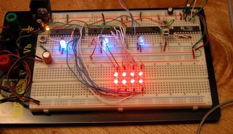
Things are moving along … With my new understanding of I2C master/slave communications, I’ve started work on larger arrays and finding the best way to manage the array and communicate the data to the host PC.

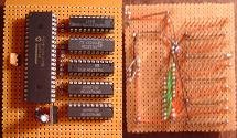
Above is the latest iteration of the project… and here is a lengthy description of what you’re seeing:

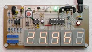
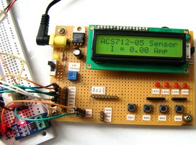
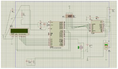
Along the top row you see six ICs, from left to right they are:

(hehe, I bet you’re thinking, I only see four ICs … well, there are six, trust me)

#1
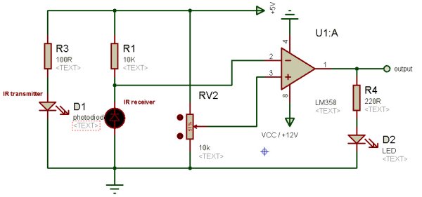
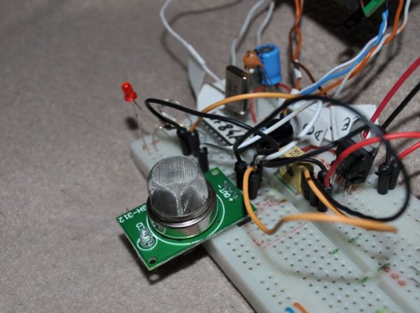
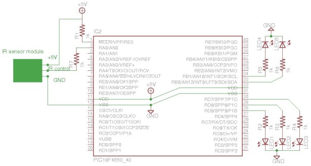
Power Supply – 7805 – This is a regulated 5 volt power supply, with some filter caps, buffering caps and a power-on led. The 7805 is infact an integerated circuit, just disguised as a transistor.LED Sensors

#2
“SlaveA” – PIC16F876A – This is one of my slave microcontrollers … it autonomously scans its row (the bottom row) in the array with blistering speed, approx 500 uSec per pixel in the array, so 2 mSec total – which is kind of slow actually, as I add more lights to the array, the responsiveness of the array grows … I can probably shorten my sample time now. The blue LED indicates the slave is operational and the program is running.

#3
“SlaveB” – PIC16F876A – This is the second slave microcontroller, which scans the top row of leds. It is running the same program as SlaveA, but with a different slave address.

#4
“Master” – PIC18F252 – This is the third microcontroller, playing the master roll. It polls the slaves every 100msec for an update, and feeds that data to the host PC. This microcontroller is severe overkill for the job its doing, but these are the PICs i had on hand, so thats how the chips fell (har har har). The blue led indicates the master is polling a slave (in real-time, the led blinks very fast)

#5
“Clock” – DS1065T-060 – This is a digital clock generator from Dallas. It is programmed to generate any clock frequency I want, currently provideing a 20mHz clock that is used by all three pics. Although not as accurate as a crystal, it does provide better temperature stability … the only reason I am using it is to save board space (and the fact I obtained a sample of one from Maxim a long time ago but never used it) … three separate crystals and their associated load capacitors would have taken up way too much board space. The DS1065 is the first TO-92 package (on the left). Next to it is a regular 2n2222 transistor which controls the MCLR (reset) line on the slaves)

#6
“Interface” – MAX233 – This is a Maxim RS232 line driver IC … The MAX233 is very similar to the popular MAX232 except it requires no external capacitors for its voltage doubler circuit, again to save board space. This chip boosts the cmos level serial data from the “master” pic to TTL level for transmission to the host pc.

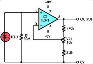
Operation of the slaves:

Each slave normally runs in a infinite loop, sampling the LED sensors as fast as it can and storing their values in a memory buffer. When a polling request is received from the master, an interrupt is generated which branches out of the sampling loop. I2C commands are pretty complex on paper, but merely a matter of setting and clearing bits in the digital world, so at 20mHz the pic handles them with lightning speed. Here is the blow by blow of the most complex series of commands, a multi-byte read

1) Master sets a “start condition” which basicly places a certain state on the bus

2) Master sends the slave address onto the bus with the read flag cleared… a slave address is the seven most significant bits of a byte (7:1), with the least signifcant bit (0) reserved for a read flag.

3) The I2C hardware in the slaves simultaniously receive this address, and compare it to their internally programmed addresses. The slave matching the address then sends an acknowledge bit on the bus.

4) Master receives the acknowledge bit and sends a command byte. Since the start condition is still present, the last slave addressed acknowledges receipt of the byte by sending an ack bit. This command byte is $04 in my application.

5) Slave receives the command, executes it and sends an acknowledge. The command $04 tells the slave to copy the ADC buffer to the transmit buffer.

5) Master receives the ack and sets a “restart condition”, which causes all the slaves to actively watch the bus for a slave address.

6) Master sends the slave address this time with the read flag set.

7) Slave matching the address sends an acknowledge. It then sends the first byte of the transmit buffer, without further prompting from the master.

8) Master receives the first data byte, and stores it in the receive buffer. The master sends an acknowledge.

9) The slave last addressed (since bus state is still START) sends the second byte in its transmit buffer.

10) Master receives the byte, stores it in its buffer, and sends an ack.

11) steps 9 and 10 repeat until the master sends an NACK and sets the bus state to STOP. This tells the slave to stop sending bytes.

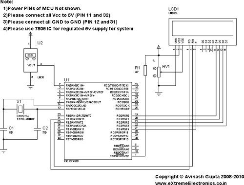
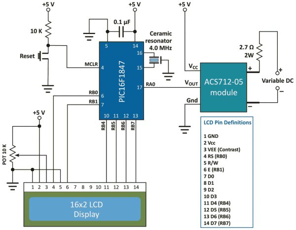
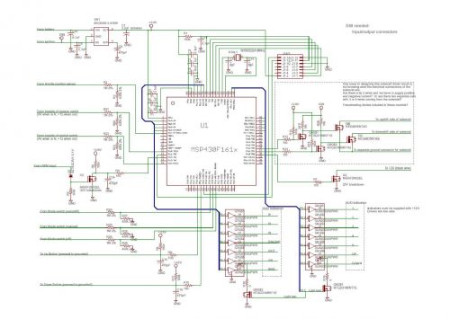
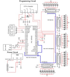
each of these steps takes a tiny fraction of a second … the entire transaction is comprised of a multitude of commands and data going both ways and is finished in the blink of an eye, indicated by a fast flashing of the masters’ status led, which blinks twice (once for each slave), but the blinking repeats so fast, it looks as if the led is solid on.LED Sensors schematic

If you’ve made it this far, congrats!

It is interesting to point out (not that I’ve seen any evidence of it on the host pc), that there is some lag introduced by the i2c routines in the ADC sampling process. Since i2c transactions are not just simple “one shot” commands, the slave is continuing to do ADC sampling while waiting for the next event from the master. This is acheived through the use of interrupts. whenever the slave is in the ADC loop, it gets pulled out to talk to the master, but since each time it talks to the master is only a very brief instant, its spending 99% of its time in the ADC loop. however, by me copying the ADC buffers to a transmit buffer only once during a transaction, the data in the buffer is ‘stale’ by the time it gets requested by the master. I’m going to look into ways of directly interfacing the i2c routines with the ADC buffers, which should let the master receive the freshest data possible. The problem here is, the ADC buffer is eight double-byte (word) values (only which four are actually used) but the transmit buffer is sixteen single-byte values, since the i2c protocol deals strictly with bytes. so the command to copy the adc buffer actually breaks the words into bytes to store in the transmit buffer. If I wanted to use the array to detect fast moving objects this would be important, but it responds to human interaction quite nicely now, even with the 100msec sampling delay imposed by visual basic. I think is due to the fact that the ‘missed’ samples are discarded instead of buffered, so the PC is still receiving real-time data from the array, just not very fast.


For more detail: LED Sensors

Current Project / Post can also be found using:

  • alchocol sensing in cars using pic16f887
  • projects based on transducer

The post LED Sensors appeared first on PIC Microcontroller.

Viewing all 136 articles
Browse latest View live


<script src="https://jsc.adskeeper.com/r/s/rssing.com.1596347.js" async> </script>